
Check the voltage drop on any run, find the smallest wire that works, or see how far you can go. Built for Canadian wiring, with the CEC 3% and 5% limits, and for 12 V and 24 V low-voltage work like maglocks, strikes and cameras.
What are you powering?
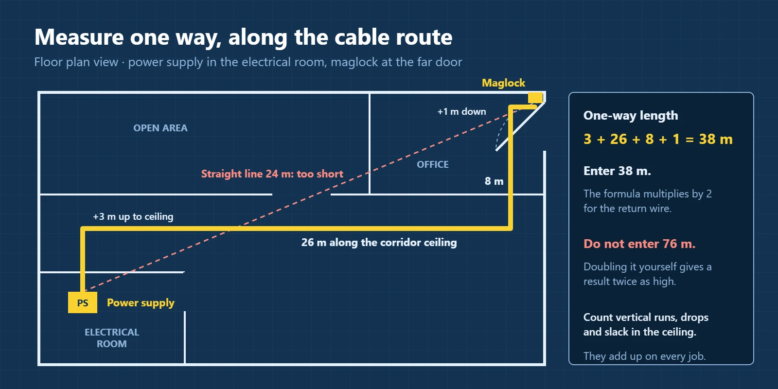
Measure from the panel or power supply to the load, along the cable route. Don’t double it. The formula counts the return wire.
Advanced settings
Warmer wire has more resistance. Use 1.0 power factor for heaters, lights and electronics, and about 0.85 for motors. Steel conduit adds a little reactance on AC.
What each setting means
| Setting | What to enter |
|---|---|
| Power type | DC for batteries, solar and most lock power supplies. AC single-phase for 120 V, 240 V, 277 V and 347 V circuits and for 24 V AC camera transformers. AC 3-phase for 208 V and 600 V equipment and feeders. |
| Voltage | The supply voltage: the panel voltage, or the output of the power supply or transformer. For three-phase, use the line-to-line voltage (208 V, 480 V, 600 V). |
| Load | The current the load actually draws, or its wattage. If you don’t know it, the CEC uses 80% of the breaker or fuse rating. Tap “Use 80% of the breaker” to fill it in. |
| One-way length | The cable route from the panel or supply to the load, not the straight line and not the round trip. |
| Wire size | AWG or kcmil, with the metric area shown beside it. Switch to Wire size mode and the calculator picks the smallest size that passes. |
| Allowed drop | 3% for one feeder or branch circuit, 5% for the whole run from the service to the load, 10% for most 12 V and 24 V devices, or your own figure. |
| Advanced | Conductor temperature, power factor, steel conduit and parallel conductors. The defaults suit most jobs. |
What voltage drop is, and why it matters
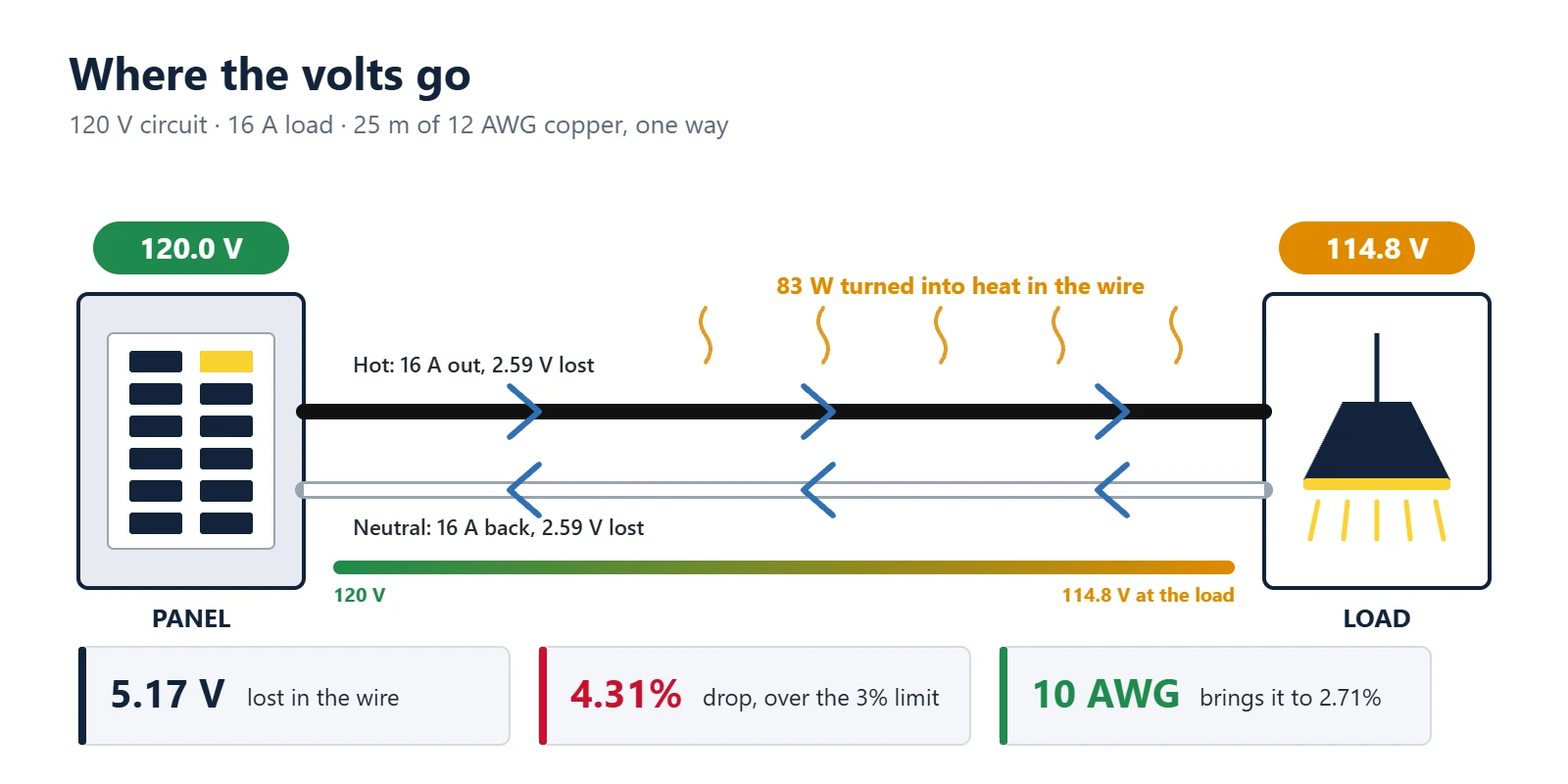
Every wire has some resistance. When current flows through it, part of the voltage is used up pushing the current along the wire and turns into heat. The load at the far end gets less voltage than the panel or power supply puts out. That difference is the voltage drop.
A small drop is normal. A large one causes problems that are easy to blame on the equipment:
- Motors run hotter, draw more current and wear out sooner.
- LED fixtures and drivers flicker, dim or drop out at the end of a long run.
- Maglocks lose holding force, and electric strikes fail to release.
- Outdoor cameras reboot on cold nights when their heaters switch on and the current jumps.
- The wire wastes power as heat, every hour the circuit is loaded.
The voltage drop formula
For DC and single-phase AC circuits:
For balanced three-phase circuits:
Then turn it into a percentage of the supply voltage:
I is the load current in amps, L is the one-way length in metres, and R is the resistance of one conductor in ohms per metre. The 2 on single-phase and DC circuits counts the wire out and the wire back. On three-phase the return currents cancel, and the line-to-line drop is √3 (1.732) times the drop in one conductor.
Resistance comes from the conductor’s cross-section and the metal it is made of:
Here ρ is 0.01724 Ω·mm²/m for copper and 0.02826 Ω·mm²/m for aluminum at 20 °C, A is the area in mm², α is 0.00393 for copper and 0.00403 for aluminum, and T is the conductor temperature in °C. The calculator adds 2% for stranding. If you work in feet and circular mils, the same formula is often written as VD = 2 × K × I × L ÷ CM, with K about 12.9 for copper and 21.2 for aluminum at 75 °C.
On AC loads with a power factor below 1, such as motors, the inductive reactance of the wire also counts. The calculator then uses the effective impedance from NEC Chapter 9, Table 9: Z = R × cos θ + X × sin θ. At a power factor of 1, Z is simply R.
Three worked examples
1. A 120 V circuit on a 20 A breaker, 25 m away
The load isn’t known, so the CEC method uses 80% of the breaker: 16 A. 12 AWG copper at 75 °C has a resistance of 6.46 Ω/km, or 0.00646 Ω/m.
5.17 V ÷ 120 V × 100 = 4.31%
That is over the 3% limit. 10 AWG (0.00407 Ω/m) brings it to 3.25 V, or 2.71%. The other option is to keep 12 AWG and shorten the run to about 17.4 m.
2. A 12 V DC maglock, 45 m from the power supply
The lock draws 0.5 A. The run uses 18 AWG copper, which is 0.0230 Ω/m at 40 °C.
1.04 V ÷ 12 V × 100 = 8.64%, so the lock sees 10.96 V
That is inside a 10% device tolerance, but with almost nothing to spare. 16 AWG cuts it to 0.65 V (5.44%). A better fix is to run the lock at 24 V: the current halves to 0.25 A, the same 18 AWG drops only 0.52 V, and that is 2.16% of 24 V. Doubling the voltage cut the percentage to a quarter.
3. A 600 V three-phase feeder, 100 A, 150 m in steel conduit
The load has a power factor of 0.9. For 3 AWG copper at 75 °C, R is 0.802 Ω/km and the reactance in steel conduit is 0.194 Ω/km.
1.732 × 100 A × 150 m × 0.000806 Ω/m = 20.9 V
20.9 V ÷ 600 V × 100 = 3.49%
Over 3%. 2 AWG copper brings it to 17.0 V, or 2.83%, and cuts the heat lost in the feeder from about 3.6 kW to 2.9 kW at full load.
Voltage drop limits in Canada: CEC Rule 8-102
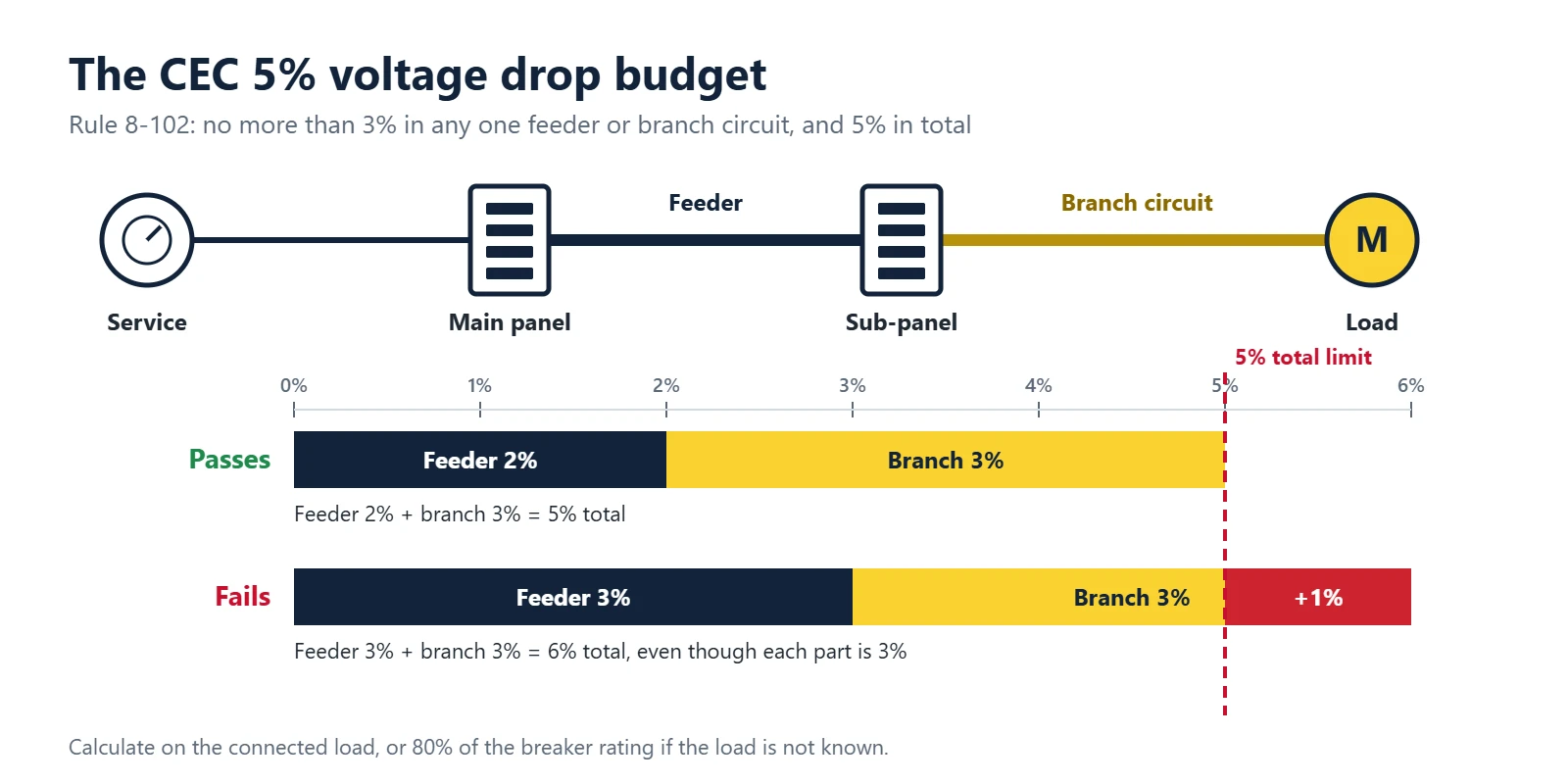
In Canada, voltage drop is a code requirement, not a suggestion. Rule 8-102 of the Canadian Electrical Code sets two limits and tells you which load to calculate with.
Maximum in any one feeder or branch circuit.
Maximum in total, from the supply side of the consumer’s service to the point of use.
Of the breaker or fuse rating, used as the load when the connected load isn’t known.
The two limits work together. A feeder at 2% leaves 3% for the branch circuit. A feeder at 3% leaves only 2% for the branch circuit, even though 3% would be allowed on its own. When you check a branch circuit, look at the feeder that serves the panel too.
Ontario’s Electrical Safety Authority explains how this is applied in dwellings in Bulletin 8-6-5. Three points from it are worth knowing:
- The calculation uses the connected load if it is known, or 80% of the rating of the overcurrent device protecting the circuit.
- In a dwelling unit, lighting and general-use branch circuits rated 20 A or less at 120 V can be checked against the maximum lengths in Table 68 instead. Appliance circuits, kitchen counter receptacles and heating and cooking circuits are excluded and still need the full calculation.
- If the service and feeder conductors to a combination service panel are shorter than 20 m, they can be left out, and the branch circuits may then use up to 5%.
The code’s own lookup method is Table D3, which lists the distance for a 1% drop at 120 V and scales it for other voltages, percentages and conductor temperatures. This calculator works from conductor resistance instead, so it covers any voltage, length and size, and gives the same answer: set 12 AWG, 16 A, 120 V, a 1% limit and 60 °C, and Max distance returns the 6.1 m that Table D3 lists.
How far common circuits can run at 3%
| Breaker | Copper wire | Load (80%) | 120 V | 208 V | 240 V | 347 V |
|---|---|---|---|---|---|---|
| 15 A | 14 AWG | 12 A | 14.6 m (48 ft) | 25.3 m (83 ft) | 29.2 m (96 ft) | 42.2 m (138 ft) |
| 20 A | 12 AWG | 16 A | 17.4 m (57 ft) | 30.2 m (99 ft) | 34.8 m (114 ft) | 50.3 m (165 ft) |
| 30 A | 10 AWG | 24 A | 18.4 m (61 ft) | 32.0 m (105 ft) | 36.9 m (121 ft) | 53.4 m (175 ft) |
| 40 A | 8 AWG | 32 A | 22.0 m (72 ft) | 38.1 m (125 ft) | 44.0 m (144 ft) | 63.6 m (209 ft) |
| 50 A | 6 AWG | 40 A | 28.0 m (92 ft) | 48.5 m (159 ft) | 56.0 m (184 ft) | 80.9 m (266 ft) |
| 60 A | 6 AWG | 48 A | 23.3 m (77 ft) | 40.4 m (133 ft) | 46.6 m (153 ft) | 67.4 m (221 ft) |
Maximum one-way length for a 3% drop on a single-phase circuit, copper at 75 °C, load at 80% of the breaker. 208 V is a two-wire circuit between two phases. Breaker and wire pairings are typical copper choices, not an ampacity check.
Canada and the US compared
| Canada (CEC Rule 8-102) | US (NEC) | |
|---|---|---|
| Status | Mandatory code rule | Informational notes, a recommendation in most cases |
| One feeder or branch circuit | 3% maximum | 3% recommended for branch circuits |
| Service or feeder to the load | 5% maximum | 5% recommended for feeder plus branch |
| Load to calculate with | Connected load, or 80% of the breaker rating | Left to the designer |
| Units on drawings | Metres, AWG and kcmil, mm² in tables | Feet, AWG and kcmil |
The calculator works for both. Switch to feet and keep the 3% and 5% settings for a US job.
Voltage drop on 12 V and 24 V low-voltage runs
Low-voltage circuits are where voltage drop bites hardest. Losing 1 V on a 120 V circuit is 0.8%. Losing the same 1 V on a 12 V maglock circuit is 8.3%. Access control, camera and LED runs are also long and use thin wire, so a run that looks fine on paper can leave a lock buzzing or a strike that won’t release.
There is no single code percentage for these devices. The practical limit is the operating range on the device’s data sheet. Many locks, strikes and controllers are rated to work within about 10% of nominal, so the low-voltage presets use 10%. Check the cut sheet for the exact figure.
Maximum one-way distance at a 10% drop
| 12 V DC | 0.25 A | 0.5 A | 1 A | 2 A |
|---|---|---|---|---|
| 22 AWG | 41.2 m (135 ft) | 20.6 m (68 ft) | 10.3 m (34 ft) | 5.1 m (17 ft) |
| 20 AWG | 65.5 m (215 ft) | 32.7 m (107 ft) | 16.4 m (54 ft) | 8.2 m (27 ft) |
| 18 AWG | 104 m (342 ft) | 52.1 m (171 ft) | 26.0 m (85 ft) | 13.0 m (43 ft) |
| 16 AWG | 166 m (543 ft) | 82.8 m (272 ft) | 41.4 m (136 ft) | 20.7 m (68 ft) |
| 14 AWG | 263 m (864 ft) | 132 m (432 ft) | 65.8 m (216 ft) | 32.9 m (108 ft) |
| 12 AWG | 419 m (1374 ft) | 209 m (687 ft) | 105 m (343 ft) | 52.3 m (172 ft) |
| 24 V DC | 0.25 A | 0.5 A | 1 A | 2 A |
|---|---|---|---|---|
| 22 AWG | 82.4 m (270 ft) | 41.2 m (135 ft) | 20.6 m (68 ft) | 10.3 m (34 ft) |
| 20 AWG | 131 m (430 ft) | 65.5 m (215 ft) | 32.7 m (107 ft) | 16.4 m (54 ft) |
| 18 AWG | 208 m (683 ft) | 104 m (342 ft) | 52.1 m (171 ft) | 26.0 m (85 ft) |
| 16 AWG | 331 m (1087 ft) | 166 m (543 ft) | 82.8 m (272 ft) | 41.4 m (136 ft) |
| 14 AWG | 527 m (1728 ft) | 263 m (864 ft) | 132 m (432 ft) | 65.8 m (216 ft) |
| 12 AWG | 837 m (2747 ft) | 419 m (1374 ft) | 209 m (687 ft) | 105 m (343 ft) |
Copper at 40 °C, two-wire DC. Divide the distance by the number of devices sharing the same pair, or add their currents in the calculator.
A few habits keep low-voltage runs reliable:
- Use 24 V where the device allows it. Half the current and twice the voltage cut the percentage drop to a quarter on the same wire.
- Add up shared loads. Two maglocks on a double door draw twice the current on the same pair.
- Use the right conductors. Composite access control cable usually has an 18 AWG pair for lock power. Don’t power a lock over the 22 AWG reader conductors.
- Size camera runs for the heater. A 24 V AC outdoor camera can draw several times its daytime current when the heater runs in winter.
- Put the supply closer. A power supply in the IDF or at the door beats a long run from the main closet.
- Measure the supply. Check the actual output with a meter. Some battery-backed supplies sit slightly above nominal, which gives a little headroom.
For door hardware power and cabling, see our guide to commercial door hardware for access control and the access control wire gauge guide. PoE devices are different: the power runs over the Cat6 pairs and the switch budget matters too, so use the PoE power calculator for those.
How to reduce voltage drop
- Use a larger wire. Every three AWG sizes doubles the copper area and halves the resistance. 12 AWG to 10 AWG cuts the drop by about 37%.
- Raise the voltage. The same power at 240 V instead of 120 V draws half the current, and the percentage drop falls to a quarter. 347 V and 600 V lighting and equipment circuits exist for the same reason.
- Shorten the run. Drop is directly proportional to length. A subpanel or a local power supply near the loads can fix several circuits at once.
- Choose copper. Aluminum has about 1.65 times the resistance of copper of the same size.
- Run conductors in parallel. On large feeders, two sets of conductors per phase halve the resistance. Set this under Advanced.
- Split the load. Two circuits carrying half the current each have half the drop.
Wire resistance table
These are the resistance values the calculator uses at 75 °C. Multiply by 2 × current × one-way length for single-phase and DC, or by 1.732 × current × length for three-phase.
| Size | Area (mm²) | Copper Ω/km | Copper Ω/1000 ft | Aluminum Ω/km | Aluminum Ω/1000 ft |
|---|---|---|---|---|---|
| 22 AWG | 0.326 | 65.70 | 20.02 | ||
| 20 AWG | 0.518 | 41.32 | 12.59 | ||
| 18 AWG | 0.823 | 25.99 | 7.920 | ||
| 16 AWG | 1.309 | 16.34 | 4.981 | ||
| 14 AWG | 2.081 | 10.28 | 3.133 | ||
| 12 AWG | 3.309 | 6.464 | 1.970 | 10.64 | 3.244 |
| 10 AWG | 5.261 | 4.065 | 1.239 | 6.694 | 2.040 |
| 8 AWG | 8.366 | 2.557 | 0.7792 | 4.210 | 1.283 |
| 6 AWG | 13.3 | 1.608 | 0.4901 | 2.648 | 0.8070 |
| 4 AWG | 21.2 | 1.011 | 0.3082 | 1.665 | 0.5075 |
| 3 AWG | 26.7 | 0.8019 | 0.2444 | 1.321 | 0.4025 |
| 2 AWG | 33.6 | 0.6359 | 0.1938 | 1.047 | 0.3192 |
| 1 AWG | 42.4 | 0.5043 | 0.1537 | 0.8305 | 0.2531 |
| 1/0 AWG | 53.5 | 0.3999 | 0.1219 | 0.6586 | 0.2007 |
| 2/0 AWG | 67.4 | 0.3172 | 0.0967 | 0.5223 | 0.1592 |
| 3/0 AWG | 85.0 | 0.2515 | 0.0767 | 0.4142 | 0.1262 |
| 4/0 AWG | 107.2 | 0.1995 | 0.0608 | 0.3285 | 0.1001 |
| 250 kcmil | 126.7 | 0.1688 | 0.0515 | 0.2780 | 0.0847 |
| 300 kcmil | 152.0 | 0.1407 | 0.0429 | 0.2317 | 0.0706 |
| 350 kcmil | 177.3 | 0.1206 | 0.0368 | 0.1986 | 0.0605 |
| 400 kcmil | 202.7 | 0.1055 | 0.0322 | 0.1738 | 0.0530 |
| 500 kcmil | 253.4 | 0.0844 | 0.0257 | 0.1390 | 0.0424 |
| 600 kcmil | 304.0 | 0.0703 | 0.0214 | 0.1158 | 0.0353 |
| 750 kcmil | 380.0 | 0.0563 | 0.0172 | 0.0927 | 0.0282 |
| 1000 kcmil | 506.7 | 0.0422 | 0.0129 | 0.0695 | 0.0212 |
DC resistance of one stranded conductor at 75 °C. Calculated from the conductor area and the standard resistivity of annealed copper (100% IACS) and 1350 aluminum (61% IACS). The values agree with NEC Chapter 9, Table 8 to within 0.5%. Aluminum building wire starts at 12 AWG.
Common voltage drop mistakes
- Doubling the length. The formula already counts the return wire. Enter the one-way length.
- Using the full breaker rating as the load. When the load is unknown, the CEC uses 80% of the breaker. Using 100% oversizes the wire.
- Checking the branch circuit only. A branch circuit at 3% fails if the feeder ahead of it already used more than 2%.
- Forgetting the temperature. Hot wire has more resistance. A loaded conductor at 75 °C has about 22% more resistance than at 20 °C.
- Confusing voltage drop with ampacity. Passing the voltage drop check doesn’t mean the wire can carry the current. Check the amp to wire size chart as well.
- Mixing up metric and AWG sizes. 2.5 mm² sits between 14 AWG (2.08 mm²) and 12 AWG (3.31 mm²). It isn’t a direct swap for either.
Voltage drop questions
What is the maximum voltage drop allowed in Canada?
Rule 8-102 of the Canadian Electrical Code allows a maximum of 3% in any one feeder or branch circuit, and 5% in total from the supply side of the consumer’s service to the point of use. The drop is calculated on the connected load if you know it, or on 80% of the breaker or fuse rating if you don’t.
How do I calculate voltage drop?
For DC and single-phase AC, voltage drop = 2 × current × one-way length × resistance per metre. For three-phase, replace the 2 with 1.732. Divide the result by the supply voltage and multiply by 100 to get the percentage. The calculator above does this and shows the full working under Show the math.
Is the length one way or the round trip?
Enter the one-way length, from the panel or power supply to the load along the route the cable takes. The formula already multiplies by 2 for the return wire on single-phase and DC circuits. Doubling the length yourself gives an answer twice as high as it should be.
What size wire do I need for 100 feet at 20 amps on 120 V?
With a real 20 A load, 100 feet one way at 120 V needs 8 AWG copper to stay under 3% (about 2.6%). 10 AWG gives about 4.1%. If 20 A is only the breaker size and the load is unknown, the CEC uses 16 A, and 10 AWG comes in at about 3.3%, which is still just over the limit.
How far can I run 12 gauge wire on a 20 amp circuit?
At 120 V with a 16 A load (80% of 20 A), 12 AWG copper reaches about 17 m (57 ft) one way before it passes 3%. On 240 V the same wire and load reach about 35 m (114 ft). These figures assume a loaded wire at 75 °C. A lightly loaded wire runs cooler and goes a little further.
How much voltage drop is acceptable on a 12 V or 24 V system?
Go by the voltage range on the device’s data sheet. Many 12 V and 24 V locks, strikes and controllers are rated to work within about 10% of nominal, which is why the low-voltage presets use 10%. LED strips show uneven brightness sooner, so the LED preset uses 5%. Battery and solar runs are usually held to 3% or less.
Why does three-phase use 1.732 instead of 2?
On a balanced three-phase circuit the currents in the three phases cancel at the neutral point, so there is no return current to double up. The line-to-line voltage drop works out to √3 (1.732) times the drop in one conductor, which is about 13% less than the single-phase factor of 2 for the same current.
Does aluminum wire have more voltage drop than copper?
Yes. Aluminum has about 1.65 times the resistance of copper of the same size. A rough rule is that aluminum needs to be two AWG sizes larger than copper for the same voltage drop. Switch the material in the calculator to see the exact size.
Does wire temperature change the voltage drop?
Yes. Copper resistance rises about 0.4% for every degree Celsius. A conductor at 75 °C has about 22% more resistance than the same conductor at 20 °C. The calculator uses 75 °C for building wire and 40 °C for low-voltage presets. You can change it under Advanced settings.
Does this match CEC Table D3?
Yes, within rounding. Table D3 lists 6.1 m for a 1% drop on 12 AWG copper at 16 A and 120 V. Set the calculator to 12 AWG, 16 A, 120 V, a 1% limit and 60 °C under Advanced settings, choose Max distance, and it returns 6.1 m.
Related tools and guides
- PoE power calculatorPower budget, voltage drop and distance for PoE cameras, phones and access points.
- Amp to wire size chartAmpacity for 12 V, 120 V and 240 V wiring. Check it alongside voltage drop.
- Wire gauge for access controlGauge charts for locks, strikes, readers and power supplies.
- Door hardware for access controlMaglocks, strikes, exit devices and how each is powered and wired.
- Data cable conduit fill calculatorCat6, Cat6A, fiber and low-voltage cable in EMT and PVC.
- EMT conduit fill chartConduit fill for building wire under the Canadian code.
Planning access control, cameras or new circuits in the GTA?
Cablify designs and installs structured cabling, access control and security cameras across Toronto and the GTA. Electrical work on our projects is carried out by an ECRA/ESA Licensed Electrical Contractor. See our electrical services.
Ask for a quoteThis calculator gives estimates for planning. Results depend on the inputs and assumptions shown. It doesn’t replace a design by a qualified person or the requirements of the Canadian Electrical Code, the Ontario Electrical Safety Code and your inspection authority.