
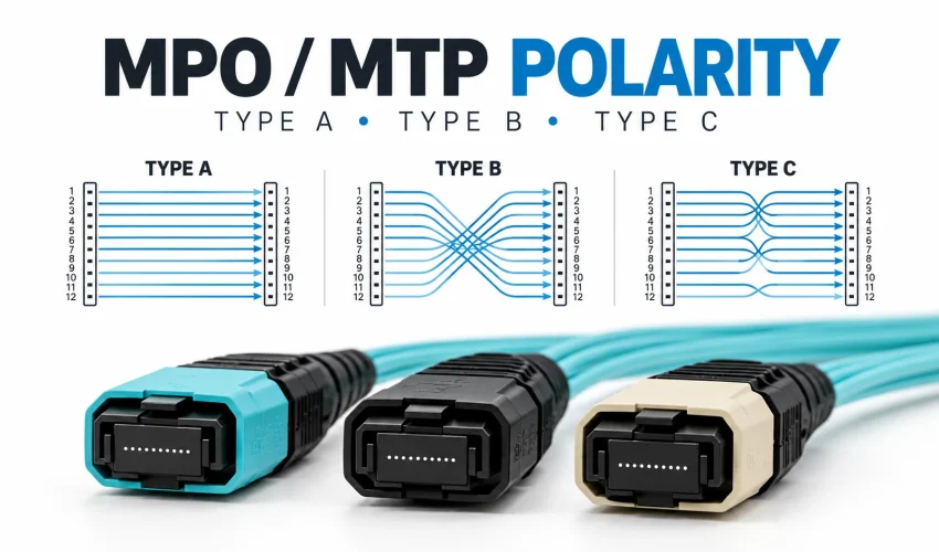
Short answer. Polarity makes sure every transmit fiber at one end reaches a receive fiber at the other. MPO cables come in three polarity types: Type A runs straight (position 1 to 1), Type B reverses the row (1 to 12), and Type C swaps each pair (1 to 2). For two 40G or 100G SR4 optics plugged straight into each other, use a Type B MPO cord with no pins at either end. If the link runs through panels and a trunk, match the method already installed.
Updated October 2026. Based on ANSI/TIA-568.3-E and manufacturer guidance, with sources at the end.
What polarity means on an MPO cable
A fiber link only works when light leaving a transmitter (Tx) lands on a receiver (Rx). On a two-fiber duplex link that is easy: a standard A-to-B patch cord connects Tx at one end to Rx at the other. If a duplex LC link will not come up, our duplex polarity fix guide covers that case.
An MPO connector usually carries 8, 12, 16 or 24 fibers in one ferrule. A 100G SR4 optic sends on four fibers and listens on four others, so every transmit lane has to land on its matching receive lane at the far end. Polarity is the set of rules that makes that happen, link after link, without anyone tracing fibers by hand.
How to read an MPO connector
Every MPO has a raised key on one side and a small white dot on the housing that marks the position 1 side. Hold the connector key up and look into the end face: positions run 1 to 12 from left to right, in the standard fiber colour order of blue, orange, green, brown, slate, white, red, black, yellow, violet, rose and aqua.
MPO or MTP? MTP is US Conec’s brand of MPO connector. It is built to the same standards (IEC 61754-7 and TIA-604-5), mates with any compliant MPO and uses the same keys, positions and polarity types. Everything on this page applies to both. Our MTP vs MPO guide covers the differences in build quality.
Type A, Type B and Type C MPO cables
An MPO trunk or patch cord is built in one of three polarity types. The type tells you where each fiber ends up at the far end.
| Type | Keys at the two ends | Where position 1 goes | Typical use |
|---|---|---|---|
| Type A (straight) | Key up to key down | Position 1 (same order) | Method A backbones, some breakout links |
| Type B (reversed) | Key up to key up | Position 12 (row reversed) | Method B and universal backbones, parallel optics |
| Type C (pairs flipped) | Key up to key down, pairs crossed | Position 2 (each pair swapped) | Older Method C duplex links |
Why does Type B reverse the row? Picture a flat ribbon of fibers terminated key up at both ends. Look into each end face in turn and the fiber on the left at one end is on the right at the other. Turning one connector key down undoes that mirror, which is why Type A runs straight.
Type is a part. Method is the whole link.
Most confusion comes from the letters being reused. The standard uses A and B for three different things:
- Cables: Type A, B or C, as above.
- MPO adapters: a Type A adapter joins two connectors key up to key down and keeps the order. A Type B adapter joins them key up to key up and reverses the order.
- Duplex patch cords: A-to-B is the standard duplex cord. A-to-A is a non-standard cord, wired the opposite way, that only Method A needs.
A polarity method is a complete recipe for a link: which trunk, which adapters, which cassettes and which patch cords. Pick one method for a building and stick to it. Mixing parts from different methods is one of the most common causes of polarity faults.
Count the flips
For MPO-to-MPO links, there is a simple check. Every Type B part in the path reverses the fiber order, and that includes adapters. Count them from one optic to the other. An odd number means transmit lands on receive and the link works. An even number means transmit lands on transmit and it does not. This rule covers Type A and Type B parts. A Type C trunk needs its own crossover cords for parallel optics, so check the maker’s drawing.
A single Type B cord between two optics is one flip, so it works. A single Type A cord is zero flips, so it does not, which is why two SR4 optics joined by a Type A cord stay dark.
The polarity methods, side by side
ANSI/TIA-568.3-E, published in September 2022, is the current standard for fiber cabling components. It keeps Methods A, B and C and adds two universal methods, U1 and U2. Here is what each one uses for a duplex link through MPO-to-LC cassettes.
| Method | Trunk | Cassettes | LC patch cords | Where Tx meets Rx |
|---|---|---|---|---|
| A | Type A | Same at both ends | A-to-B at one end, A-to-A at the other | In the one A-to-A cord |
| B | Type B | One flipped, installed as matched pairs | A-to-B at both ends | The trunk reverses the row and the paired cassette puts each port back |
| C | Type C | Same at both ends | A-to-B at both ends | Inside the trunk, pair by pair |
| U1 and U2 | Type B | Same universal cassette at both ends | A-to-B at both ends | The trunk reversal, with fibers paired so each port stays the same |
Method A
Straight trunk, same cassette at both ends, and the Tx/Rx flip comes from a single A-to-A cord at one end. It works, but the two ends need different patch cords, and someone has to know which end gets which. That is where Method A links usually go wrong.
Method B
Reversed trunk and standard A-to-B cords at both ends. For duplex links the cassette at one end has to be flipped, either a second cassette type or the same cassette mounted inverted, depending on the maker, so they are installed as matched pairs. Fluke Networks and Siemon both describe Method B as the most recommended method, and for parallel optics it is the simplest: Type B cords at both ends of a Type B trunk.
Method C
The pair swap happens inside the trunk, so both ends use the same cassette and standard cords. It suits duplex links but needs hard-to-find crossover cords for parallel optics, so it is rarely used for new work.
Universal methods U1 and U2
Added in TIA-568.3-E, these use a Type B trunk with the same cassette and the same A-to-B cords at both ends, so there are no matched pairs to keep track of. U1 uses key up to key down adapters, which also suits angled single-mode connectors. Leviton calls universal polarity the easiest option to deploy. Corning uses its own universal polarity in its EDGE8 modules, and Siemon’s standard MPO-to-LC modules are Type U1.
If you are starting a new backbone, a Type B trunk is the common thread: it carries parallel optics with Type B cords, and duplex traffic with Method B or universal cassettes. Moving later from duplex links to parallel optics is then a matter of swapping cassettes for MPO adapter panels on the same trunk.
Pins, keys and end faces
Pinned and unpinned connectors
Two guide pins keep the fibers lined up. Every connection needs exactly one pinned (male) connector and one unpinned (female) connector. Pin-to-pin and hole-to-hole connections do not work.
Transceiver ports are pinned, so any MPO cord that plugs into an optic must be unpinned. TIA-568.3-E also changed the recommended layout: trunks pinned at both ends, cassettes unpinned, and MPO patch cords unpinned at both ends. Older sites may be wired the other way, so check the gender of the installed cassette ports before ordering a new trunk.
Base-8, Base-12 and MPO-16
Most 40G, 100G and 400G parallel optics use only eight fibers of a 12-position MPO: positions 1 to 4 transmit, 9 to 12 receive, and the middle four sit empty. That is Base-8. CommScope notes that “MPO8” and “MPO12/8” mean the same thing. Building a new backbone in Base-8 means no fibers sit dark when you run SR4 or DR4 traffic over it.
Most 400G SR8 optics use an MPO-16, which has 16 fibers in a row and an offset key. It is not an MPO-12 with extra fibers, so it needs its own MPO-16 cords and adapters. The standard also allows a two-row MPO-24 version, so check the data sheet.
Flat (UPC) and angled (APC) end faces
Single-mode MPOs are polished at an 8 degree angle (APC) and have green connector bodies. Some high-speed multimode optics use APC too, including some 800G multimode modules, so read the transceiver data sheet rather than assuming. Never mate an APC connector to a flat one: the link will perform badly and the end faces can be damaged. Polarity on APC connectors also cannot be changed in the field, so APC cables have to be ordered right the first time.
For more on single-mode and multimode grades, see our guide to every type of fiber optic cable and our fiber transceivers guide.
Which MPO cable to order
Use this as a starting point, then confirm against the transceiver and cassette data sheets.
| Your link | What to order |
|---|---|
| Two 40G or 100G SR4 optics, plugged straight into each other | Type B MPO-12 cord (Base-8 is enough), unpinned at both ends, multimode, flat (UPC) |
| Two 400G DR4 optics, direct | Type B MPO-12 cord, unpinned at both ends, single-mode APC |
| Two 400G SR8 optics, direct | Type B MPO-16 cord, unpinned at both ends, APC (check the optic is MPO-16) |
| 800G optics | Check the data sheet: twin MPO-12 or single MPO-16, usually APC even on multimode, Type B, unpinned at the optic |
| Parallel link through patch panels and a trunk | Pinned Type B trunk with unpinned Type B cords at both ends; on APC, confirm the adapters are key up to key down |
| 10G or 25G duplex (LC) over an MPO backbone | Type B trunk, matching universal (U1) or Method B cassettes, A-to-B LC cords at both ends |
| One 40G or 100G port split into four 10G or 25G ports | Base-8 MPO-to-LC harness plugged straight into the switch, with the leg pairing the switch maker specifies. Through panels and a trunk, follow the cabling maker’s channel drawing. |
| Adding to an existing installation | Find out the installed method and pin layout first, then match it exactly |
Common MPO polarity mistakes
- Mixing methods. Siemon says most polarity and gender problems happen at the patch cord end of the link, where someone ordered the wrong polarity cord, often on sites that mix Method A and Method B parts.
- Type B cords on a Type A trunk. That adds up to two flips, an even number, so transmit meets transmit.
- Pin to pin. Two pinned or two unpinned connectors will not mate properly.
- APC to UPC. Angled and flat connectors do not line up, and forcing them can damage the optics.
- Unpaired Method B cassettes. Two cassettes set up the same way on one Method B trunk put every port in the wrong place.
- Dirty connectors. One dirty MPO end face affects every fiber in it at once, and dirt on the guide pins raises loss. A dirty connector can take a link down just like a polarity fault, so inspect and clean before blaming polarity.
How MPO polarity is tested and fixed
Purpose-built MPO testers check every fiber at once. Fluke Networks’ MultiFiber Pro, for example, tests all 12 fibers of an MPO in about 6 seconds and reports whether the link is Type A, B or C. VIAVI and EXFO make similar MPO test sets. Without one, a crew can use breakout cords and a light source and power meter, but polarity is only proven if the far-end position of every fiber is recorded.
Every Cablify job is Fluke tested, and full certification reports are available on request.
When a link fails, work through it in this order:
- Inspect and clean both connectors, including the guide pins.
- Check the gender at every connection and that flat and angled connectors are not mixed.
- Read the tester’s fiber map: straight, reversed or pairs swapped.
- Change the patch cord type at one end to correct the flip count.
- On some MTP and MPO connectors, such as US Conec MTP PRO, the key and pins can be changed in the field. Changing the key to fix polarity does not work on angled (APC) connectors, though on some the pins can still be changed.
- Replace a cassette only as a last resort.
Pre-terminated MPO assemblies are built to order and often cannot be returned, which is one more reason to settle polarity before ordering.
Ordering MPO cables in Canada
Whether you buy MPO cables yourself or have them built for a job, the order needs these details:
- Polarity type: A, B or C
- Connector and gender at each end: pinned or unpinned
- Fiber count and base: 8, 12, 16 or 24
- Fiber grade: OM3, OM4, OM5 or OS2
- End face polish: flat (UPC) or angled (APC)
- Length, and breakout leg length if the cable fans out to LC
- Jacket fire rating: FT4 or FT6 (see our plenum, riser and direct burial guide)
We supply custom fiber assemblies made to these specs. See ordering custom fiber cables in Canada for how it works.
MPO polarity questions
Which MPO polarity do I need for 100G SR4?
For two 100G SR4 optics connected directly, use a Type B MPO-12 cord that is unpinned at both ends. Type B maps position 1 to position 12, so each transmit lane lands on its matching receive lane. If the link runs through patch panels and a trunk, count the Type B parts in the whole path: an odd number works.
What is the difference between Type A and Type B MPO cables?
A Type A cable runs straight, with the key up at one end and down at the other, so position 1 arrives at position 1. A Type B cable has the key up at both ends, which reverses the row, so position 1 arrives at position 12. Type B is the usual choice for parallel optics such as 40G and 100G SR4.
Is MTP polarity different from MPO polarity?
No. MTP is US Conec’s brand of MPO connector. It is built to the same standards, mates with any compliant MPO and uses the same keys, positions and Type A, B and C polarity. The differences are in build quality, such as a floating ferrule and a removable housing.
Is Type C MPO polarity still used?
Rarely for new work. Type C swaps each pair of fibers inside the trunk, which suits duplex links, but parallel optics then need crossover cords that are hard to find. Most manufacturers now recommend Method B or the universal methods built on a Type B trunk.
Should an MPO cord to a transceiver be male or female?
Female, meaning unpinned. Transceiver ports are pinned, and every MPO connection needs one pinned and one unpinned connector. TIA-568.3-E also recommends pinned trunks with unpinned cassettes and unpinned MPO patch cords.
Can MPO polarity be changed in the field?
Sometimes. Swapping the patch cord type at one end is the usual fix. Some MTP and MPO connectors can be re-keyed and have their pins added or removed on site. Re-keying does not work on angled (APC) connectors, so APC cables, which include all single-mode and some multimode MPOs, need to be ordered correctly.
Planning an MPO backbone?
Cablify installs fiber cabling across Toronto and the GTA. Every job is Fluke tested, full certification reports are available on request, and the site assessment is free.
Book a free site assessmentCall 647-846-1925
More on our fiber optic installation service.
Sources
- TIA: ANSI/TIA-568.3-E published, September 2022
- Fluke Networks: 12-fiber MPO polarity
- Fiber Optic Association: testing MPO connectors and polarity
- Siemon: ANSI/TIA introduces new polarity methods
- Leviton: universal polarity in 12-fiber duplex applications
- Corning and Arista: cabling guide for 40G to 800G optics
- CommScope: MPO8 and MPO12/8, June 2026
- US Conec: MTP connector FAQ
- Siemon: master MTP polarity like a pro
- Fluke Networks: fiber polarity basics for duplex applications
- Fluke Networks: MultiFiber Pro data sheet
- Cisco: OSFP 800G transceiver modules data sheet