
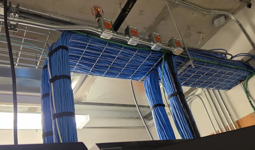
Cable tray is the part of a building’s cabling nobody notices until it is full, sagging or in the way. Pick the wrong type, hang it badly or fill it to the brim on day one, and every future cable add turns into a ceiling job. Get it right and new cable goes in from the top in an afternoon.
This guide covers every common type of cable tray, the components that make up a complete system, the finishes, how to size a tray for data cable, the Canadian code and standards that apply, and how a tray route is installed. We wrote it for facility managers, general contractors, IT leads and designers working on commercial and industrial buildings in Ontario. The electrical rules come from the Canadian Electrical Code, not the US code most online guides quote.
Short answer
A cable tray is an open, rigid support system that carries cables along a building’s main routes. The common types are ladder, ventilated trough, solid bottom, channel, wire mesh (basket) and single rail, plus cable runway inside network rooms. A complete system also needs fittings (elbows, tees, crosses, reducers and vertical bends), splice hardware, supports, covers, dividers, drop-outs and bonding hardware.
For data cabling, ANSI/TIA-569 limits fill to 50% of the tray’s cross-section and 150 mm of cable depth, and wire basket is supported at least every 1.5 m. In Canada, the Canadian Electrical Code treats cable tray as a raceway and sets its clearances, load limits and bonding in Rules 12-2200 to 12-2210.
In this guide
What a cable tray is
The Canadian Electrical Code defines a cable tray as a raceway made of troughing and fittings, formed so that insulated conductors and cables can be readily installed or removed. That last part is the whole point. Conduit has to be pulled, and every change means another pull. Tray is open, so cable is laid in from the top and lifted out when it is no longer needed.
The US National Electrical Code sees it differently. Under NEC Article 392, cable tray is a support structure, not a raceway. That difference changes which rules apply to the cables inside it, so a US spec or blog post can steer a Canadian job wrong, especially on mixing power and data.
Most buildings use tray for the main routes and something lighter for the branches. A corridor tray feeds J-hooks or conduit to each room, and cable runway carries cable over the racks inside the network room. If you are still choosing between those pathways, our cable tray installation page compares tray, conduit, J-hooks and ladder rack side by side.
Types of cable tray
Tray types differ in what the cable sits on. That decides how well small cables are supported, how much air reaches large ones, how easy it is to add cable later and how far the tray can span between supports.
| Type | What the cable sits on | Typical sizes | Best fit | Data cabling note |
|---|---|---|---|---|
| Ladder | Rungs between two side rails, usually 150, 230 or 300 mm apart | 150 to 900 mm wide; 75 to 200 mm side rails; 3 m to 6 m and longer | Power feeders, backbones, plants, long spans | Use 150 mm rungs so small cables are not bent over each rung |
| Ventilated trough | Slotted or perforated bottom, or rungs about 100 mm apart | Same widths as ladder | Control and instrumentation cable, mixed small cables | Near-continuous support with some airflow |
| Solid bottom | Solid sheet bottom, often with a cover | Same widths as ladder | Exposed areas, dust, falling debris, specs that call for enclosure | Holds heat; slower to add cable |
| Channel | One-piece U channel, solid or ventilated | 75 to 150 mm wide | Drops and short branches off a main tray | A tray version of a single conduit drop |
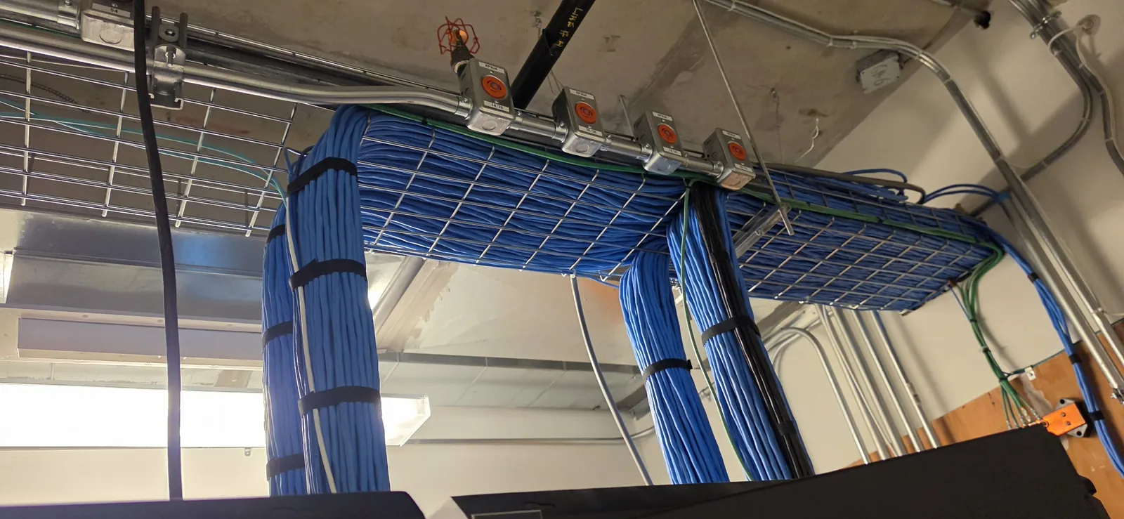
| Wire mesh (basket) | Welded steel wire grid, usually 50 x 100 mm | 50 to 600 mm wide, 30 to 150 mm deep, 3 m lengths | Data, fiber, security, light power | The usual choice for structured cabling; support at least every 1.5 m |
| Single rail | Arms reaching out from one central rail | Varies by maker | Data centre rows, dense equipment areas | Cable lays in from both sides |
| Cable runway | Cross members between tubular steel stringers about 38 mm high | 150 to 600 mm wide, about 3 m lengths | MDF, IDF and server rooms | Carries cable over racks and down into them |
| Fiber raceway | Enclosed plastic duct, usually yellow | Varies by maker | Fiber patching in data centres and large equipment rooms | Keeps fiber out from under copper bundles |
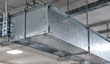
Ladder tray
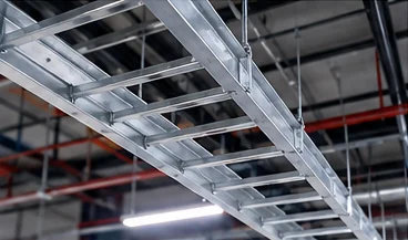
Ladder tray is two side rails joined by rungs. It is the strongest open design and spans the furthest between supports, which is why it carries power feeders and backbones through plants, warehouses and large mechanical spaces. Aluminum ladder is common in Canada because it is light, does not rust and comes in long lengths, from 3 m and 12 ft sections up to 20 ft and longer.
Rung spacing is the setting that matters most. Large power cables sit happily on rungs 230 to 300 mm apart. Small cables do not: a bundle of Cat6 on 300 mm rungs bends over every rung, and those pressure points add up over a long run. The University of Saskatchewan’s master specification handles this well, calling for 150 mm rung spacing on data and security trays and 300 mm on power trays.
Check the depth figures too. Manufacturers quote side rail height as the outside height of the tray. The usable loading depth inside is smaller, and that is the number fill calculations use.
Ventilated trough tray
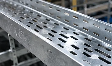
Ventilated trough has a slotted or perforated bottom, or rungs about 100 mm (4 in) apart. Small control and instrumentation cables get near-continuous support, and heat still escapes through the openings. It suits industrial runs of many small cables where ladder rungs would be too far apart and a solid bottom would trap heat.
Solid bottom tray
A solid sheet-metal bottom gives the most physical protection from dust, drips, falling debris and passing hands. It also holds heat, collects whatever falls into it, and slows down adds and removals, because cable cannot drop out through the bottom and has to leave through a fitting or a cut-out. With a cover and proper bonding it can be part of a noise-control plan, but the cover, the joints and the distance from power sources matter more than the bottom alone.
Channel tray
Channel tray is a one-piece channel, usually 75 to 150 mm wide, with a solid or ventilated bottom. It takes the short branch from a main tray to a panel, a machine or a group of devices. Think of it as a single conduit drop that you can still lay cable into.
Wire mesh (basket) tray
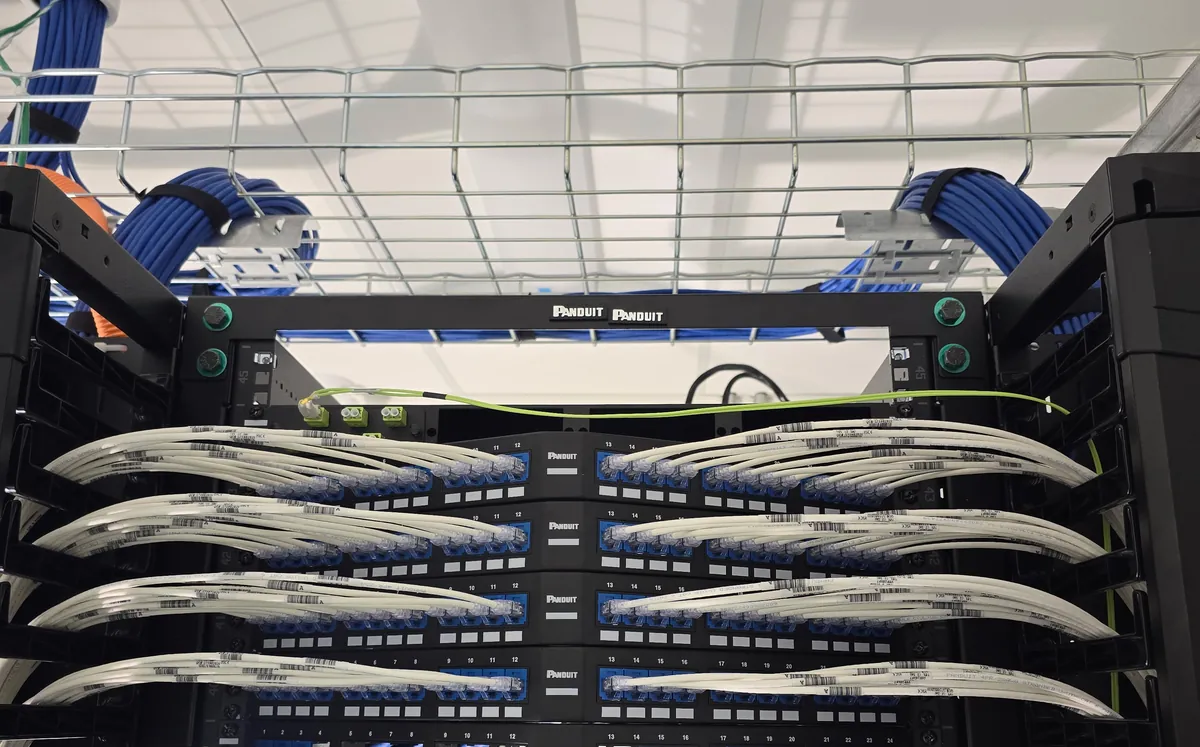
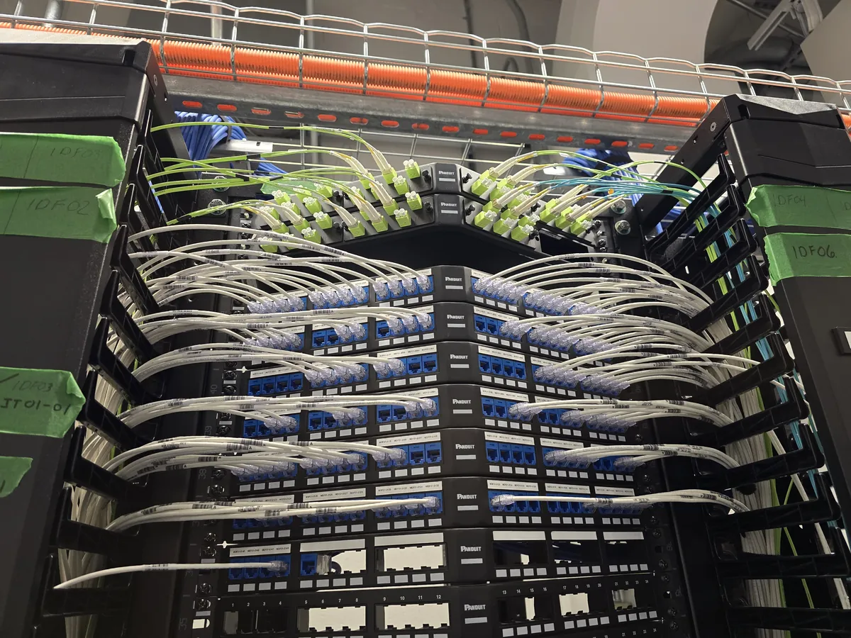
Wire mesh tray, also called basket or wire basket tray, is a grid of welded steel wires formed into a U. It is the tray most structured cabling goes into and the one we install most often. Names you will see on drawings and in distributor listings include Cablofil (Legrand), FlexTray (Eaton B-Line), Wyr-Grid (Panduit) and WBT.
The grid is usually 50 x 100 mm (2 x 4 in). Hubbell, for example, uses 5 mm wire on its smaller sizes and 6 mm on larger ones, with a T-weld so wire ends do not snag cable jackets. Widths run from about 50 mm to 600 mm and depths from about 30 mm to 150 mm, usually in 3 m (10 ft) lengths.
Its big advantage is that it is shaped on site. Elbows, tees, reducers and drops are made by cutting wires, bending the tray and joining it with splice hardware, so the route follows the building without a pile of factory fittings. A 3 m section is light enough for one installer to lift into place.
The trade-offs are shorter spans than ladder tray, little protection against impact, and tighter support spacing. For telecom cabling, TIA-569 calls for wire basket to be supported at least every 1.5 m (5 ft).
Single rail and centre spine tray
Single rail tray hangs from one central rail or rod, with arms reaching out on both sides. Cable is laid in from either side without threading it under anything, which is why it shows up over data centre rows and in dense equipment areas. It carries less than a two-rail tray of the same width, and the load should be kept roughly even on both sides.
Cable runway (ladder rack)
Inside MDF, IDF and server rooms, the pathway is usually cable runway, also sold as ladder rack. It looks like a light ladder: two tubular steel stringers about 38 mm (1.5 in) high with cross members between them, in widths of 150, 300, 450 and 600 mm (6, 12, 18 and 24 in) and lengths just under 3 m (10 ft). Chatsworth, nVent Hoffman, Ortronics and B-Line all make it.
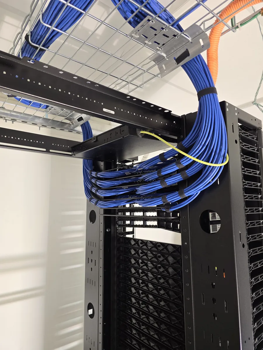
Runway is built for rooms, not corridors. It bolts to the tops of racks, runs to the wall on wall angle kits or triangular brackets, hangs from threaded rod kits mid-span, and turns with corner brackets, E-bends and radius bends. Where cable leaves the runway into a rack, a radius drop (a curved cross member or stringer) stops the bundle folding over a square edge. Runway sections are bonded together and back to the room’s telecommunications grounding busbar, usually with #6 AWG ground strap kits across the splices.
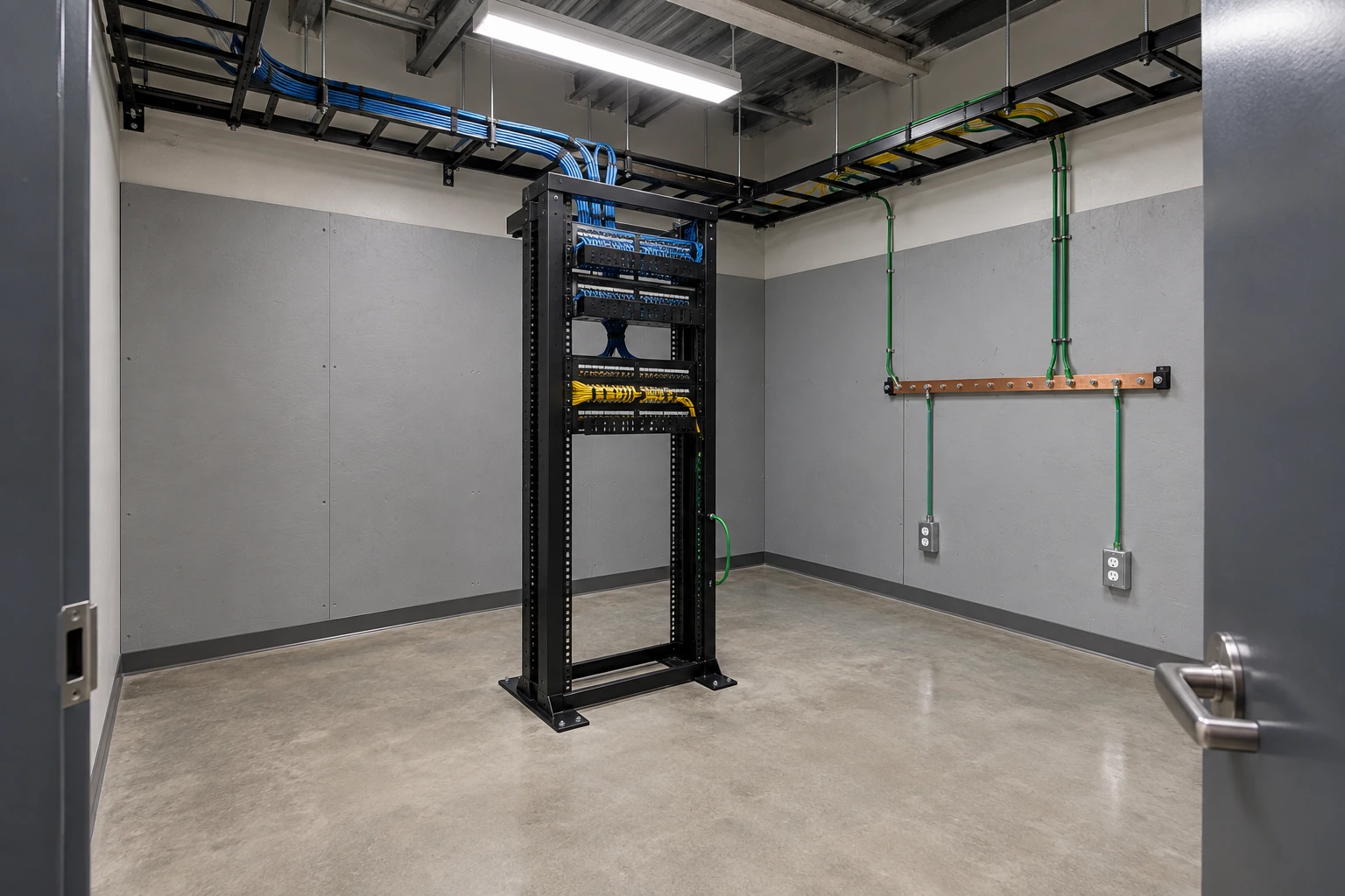
For how runway fits into the rest of a network room, see our guides to MDF and IDF rooms and server rack sizes.
Fiber raceway and innerduct
Data centres and large equipment rooms often add a separate plastic fiber raceway, usually yellow, above or beside the copper tray. It keeps patch cords and small fiber cables from being buried under heavy copper, and its fittings are shaped to the fiber’s bend radius. On smaller jobs, innerduct laid in the basket tray does much the same job for a lot less money.
Every tray type above, except runway, also comes in aluminum, stainless steel or fiberglass. The materials section covers which to pick.
Cable tray components
A cable tray system is a kit of parts, and distributor catalogues split it into tray and fittings. Graybar’s cable tray and fittings section, for example, lists more than 5,000 products from B-Line (Eaton), Cablofil (Legrand), Chatsworth, Hubbell, Panduit, nVent Hoffman, Cope and others. Sorted by the job each part does, they fall into six groups.
- End plate
- Straight section
- Splice plate
- Divider (barrier strip)
- Horizontal tee
- Reducer
- Cover
- 90° horizontal elbow
- Trapeze support on threaded rod
- Vertical outside elbow (turns the run down)
- Vertical inside elbow (turns the run level again)
- Waterfall drop into a rack
- Bonding jumper across a splice
1. Straight sections
Straight sections make up most of a run. Ladder and trough come in 3 m and 6 m lengths, or 10, 12, 20 and 24 ft in imperial, with some aluminum ladder available longer still. Wire basket usually comes in 3 m (118 to 120 in) lengths. Runway comes in pieces just under 3 m that are cut to fit.
Pick the section length to suit the support spacing, not the other way round. NEMA VE 2 says the support span should not be longer than the straight section, so there is never more than one splice between two supports.
2. Fittings
Fittings change the direction, level or width of a run. On ladder and trough they are factory-made. On wire basket most of them are formed on site from straight sections, though kits exist for tees and bends.

| Fitting | What it does | Notes |
|---|---|---|
| Horizontal elbow (30°, 45°, 60°, 90°) | Changes direction on the same level | Common radii are 300, 600 and 900 mm (12, 24 and 36 in). The radius must not be tighter than the bend radius of the largest cable |
| Horizontal tee | Branches off one side | Support near each of the three openings |
| Horizontal cross | Branches off both sides | Typical at corridor intersections |
| Horizontal wye | Branches at 45° | Gentler on large cables than a tee |
| Reducer (straight, left, right) | Joins two widths | Left and right reducers keep one rail straight along a wall |
| Vertical outside elbow | Turns the run downward; cable rides over the outside of the curve | At the top of a run, support both ends |
| Vertical inside elbow | Turns the run back to level, or upward; cable sits on the inside of the curve | At the bottom of a run, support the top end and within about 600 mm of the lower end |
| Vertical tee and vertical cross | Branch up or down from a run | Used at risers and shaft entries |
| Adjustable elbows and offsets | Small changes of angle or level found on site | Hinged splice plates do the same on straight runs |
| Drop-out, waterfall and radius drop | Lets cable leave the tray over a curved edge | Use at every rack and device drop |
| End plate or end cap | Closes the end of a run | Protects cable and people from cut ends |
3. Splice and joining hardware
Splice plates bolt sections and fittings together and carry the load across the joint. On ladder and trough jobs you will see standard splice plates, expansion splice plates that allow about 25 mm (1 in) of movement, adjustable splices that hinge horizontally or vertically, reducing splices and offset splices. Wire basket uses its own hardware: splice washers and bolts, clip-on splicers such as Cablofil’s Fast Splice, and splice washer kits. Runway uses butt-splice, junction-splice and swivel splice kits.
Use the maker’s hardware with the maker’s tray. Splices are part of the tested load rating and, on many systems, part of the bonding path. Many specifications go further and require tray, fittings and accessories from a single manufacturer.
4. Supports and hangers
Supports carry the tray to the building structure. Four types cover most jobs:
- Trapeze hanger. Two threaded rods with a length of strut across the bottom. The standard for ladder and wide basket runs, and the easiest way to carry two or three tiers.
- Centre hanger. A single rod into a bracket under the centre of the tray, such as Cablofil’s FAS profile bracket. Fast and tidy, and it leaves both sides open for laying in cable, but it suits lighter loads and narrower trays.
- Wall bracket. A cantilever or triangular bracket off a wall or column. Common along corridor walls and in telecom rooms.
- Rack-mounted. Runway or basket fixed to the tops of racks and cabinets with rack-to-runway kits, plus wall-to-rack kits to bridge the gap to the wall.
Under raised floors, basket tray sits on floor stands or pedestals instead. Hold-down clamps or plates fix the tray to each support so it cannot slide or lift. Rod size, anchors and beam clamps depend on the structure and the load; 3/8 in threaded rod covers most data tray, and heavier ladder trapezes are sized from the load.
5. Covers, dividers and cable management accessories
- Covers. Solid, ventilated or peaked (to shed water and snow outdoors), fixed with cover clamps. They protect against falling objects, sun and ice, but they also trap heat, which matters for power cable ratings.
- Dividers or barrier strips. Run the length of a tray to separate power from data, or one system from another.
- Drop-outs, waterfalls and radius drops. Curved edges that protect the bend radius where cable leaves the tray.
- Conduit adapters and clamps. Join conduit to the tray with a bonded, supported fitting.
- Cable retaining posts, end caps and edge protectors. Keep cable on runway and cover sharp ends.
- Threaded rod covers. Stop cable rubbing on rod threads and tidy up exposed rods.
6. Bonding and grounding hardware
Grounding clamps and lugs, bonding jumpers across expansion splices and gaps, and ground strap kits for runway. Typical catalogue items include tin-plated aluminum tray grounding clamps, basket tray grounding lugs for 6 to 1/0 AWG conductors, and #6 AWG runway ground strap kits. On aluminum tray, use tin-plated connectors. Bare copper bolted straight to aluminum corrodes.
Materials and finishes
The finish decides how long the tray lasts where it is installed. Distributor filters show the usual choices: aluminum, pre-galvanized, hot-dip galvanized, electro-zinc (zinc plated), powder-coated, stainless steel and fiberglass.
| Material or finish | What it is | Where it fits | Watch for |
|---|---|---|---|
| Electro-zinc (EZ), zinc plated | Steel electroplated with a thin zinc layer after forming | Dry indoor spaces: offices, telecom rooms, most data centres | Indoor use only |
| Pre-galvanized (PG) | Steel galvanized at the mill before forming, about 19 µm of zinc (ASTM A653 G90) | Indoor commercial and light industrial | Cut edges and welds are less protected |
| Hot-dip galvanized (HDG) after fabrication | Finished tray dipped in molten zinc, about 65 µm (ASTM A123), which also coats edges and welds | Outdoors, parking garages, loading docks, wet and salty areas | Heavier and rougher; touch up cut ends with zinc-rich paint |
| Aluminum | 5000 and 6000 series alloys, naturally corrosion resistant | Rooftops, plants, outdoor runs, long ladder spans | Galvanic corrosion with bare copper |
| Stainless steel 304 or 316 | No coating needed; 316 adds molybdenum for chloride resistance | Food, beverage and pharmaceutical plants, washdown, chemical and coastal sites | Cost; use 316 where salt or chlorides are present |
| Powder-coated | Steel with a polyester or epoxy powder finish, often black | Data centres, exposed ceilings, colour-coded systems | Chips need touch-up |
| Fiberglass (FRP) | Pultruded polyester or vinyl ester resin | Corrosive chemical areas, wastewater, where a non-conductive tray is needed | Its own load tables and standards (NEMA FG 1, CSA C22.2 No. 126.2) |
The coating thickness is the difference that matters outdoors. ABB’s cable tray technical guide puts hot-dip galvanizing at more than three times the service life of pre-galvanized steel in the same environment, because the zinc layer is over three times thicker and covers the cut edges. Around the GTA, that makes HDG, aluminum or stainless the default for parking garages and loading docks, where road salt reaches the tray every winter.
Zinc whiskers. Some data centre owners ban zinc-plated tray because of zinc whiskers, tiny metal filaments that can grow from zinc coatings, break off and short out equipment. Chatsworth, for one, recommends powder-coated or hot-dip galvanized finishes over electroplated zinc in data centres. Legrand argues that the risk from its electroplated wire tray is minimal and points out that it has supplied it for decades without a recorded incident, while still offering painted and zinc-aluminum finishes. The research is thin. If the owner has a policy, follow it. If not, powder-coated tray takes the question off the table at little extra cost.
Sizing a cable tray: fill, depth and weight
Fill
For telecom cabling, ANSI/TIA-569 sets the ceiling. Cable should take up no more than 50% of the tray’s inside cross-section, and the pile should be no deeper than 150 mm (6 in), whatever the side rail height. Fifty percent sounds generous until you see it. Round cables leave gaps between them, so a tray at 50% calculated fill already looks full. That is why designers aim for about 25% at handover, and some specifications use 40%, so the tray still has room after years of moves, adds and changes.
Fill % = (number of cables x π x OD² / 4) ÷ (inside width x usable depth) x 100
Worked example: 180 Cat6A cables at 7.6 mm OD take up 180 x 45.4 = about 8,170 mm². A 300 x 100 mm basket has 30,000 mm² inside. Fill = 27%, a sensible handover figure, with room to grow to about 330 cables before it reaches 50%.
| Inside width x usable depth | Area | Cat6 U/UTP, 6.1 mm OD | Cat6A U/UTP, 7.6 mm OD |
|---|---|---|---|
| 150 x 50 mm (6 x 2 in) | 7,500 mm² | 64 / 128 | 41 / 82 |
| 300 x 50 mm (12 x 2 in) | 15,000 mm² | 128 / 256 | 82 / 165 |
| 150 x 100 mm (6 x 4 in) | 15,000 mm² | 128 / 256 | 82 / 165 |
| 300 x 100 mm (12 x 4 in) | 30,000 mm² | 256 / 513 | 165 / 330 |
| 450 x 100 mm (18 x 4 in) | 45,000 mm² | 384 / 769 | 247 / 495 |
| 600 x 100 mm (24 x 4 in) | 60,000 mm² | 513 / 1026 | 330 / 661 |
| 450 x 150 mm (18 x 6 in) | 67,500 mm² | 577 / 1154 | 371 / 743 |
| 600 x 150 mm (24 x 6 in) | 90,000 mm² | 769 / 1539 | 495 / 991 |
Capacities are calculated from the outside diameters shown. Check your cable’s datasheet: Cat6A diameters run from about 6 mm for reduced-diameter designs to over 8 mm, and that changes the count a lot. A 300 x 150 mm tray has the same area as a 450 x 100 mm tray, but the shallower, wider tray is easier to lay cable into. For conduit instead of tray, use our data cable conduit fill calculator.
Weight and load rating
For data cable in basket tray, fill is usually the limit. Weight becomes the limit with heavy power cable, long spans, stacked tiers, wide trays full of Cat6A and anything outdoors. Cat6A U/UTP typically weighs 0.05 to 0.07 kg per metre per cable, so the 330 Cat6A cables above put roughly 20 kg on every metre of tray. Add the tray itself, the cable you expect to add later and, outdoors, ice and snow.
Load ratings have changed over the years. NEMA used to describe tray by span in feet plus a load letter: A for 50 lb/ft, B for 75 and C for 100. A 12B tray carried 75 lb/ft on a 12 ft span, and 20C carried 100 lb/ft on 20 ft. CSA uses letter classes tied to a span in metres, such as C1-3m or E-6m. Today trays are marked with an actual rated load at a stated span, and since the 2012 edition the Canadian Electrical Code requires the design load and support spacing to stay within the load/span rating on the tray’s nameplate. When you ask a manufacturer for a quote, the two numbers they want are the load in kg/m (or lb/ft) and the support spacing.
One more point from ABB’s guide: a load concentrated at mid-span deflects a tray about twice as much as the same load spread evenly. Tray is not a shelf, a walkway or a place to hang other trades’ services.
Width, depth, rung spacing and bend radius
- Depth. 50 mm basket for short branches and light runs, 100 mm for most corridor mains, 150 mm only where the cable count needs it, since 150 mm is also the maximum pile depth.
- Width. From the fill calculation plus growth. Two narrower trays (copper and fiber, or two systems) are often better than one wide one.
- Rung spacing. On ladder tray carrying data, 150 mm.
- Fitting radius. No tighter than the largest cable’s bend radius. Installed Cat6 and Cat6A U/UTP need at least 4 times the cable diameter. Fiber needs more, typically 10 times the cable diameter installed and up to 20 times while pulling.
The fiber figures and cable constructions are covered in our guide to fiber optic cable types.
Codes and standards for cable tray in Canada
Two kinds of document apply. Codes are law and an inspector enforces them. Standards and guidelines are what designers and specifications point to, and they often become contractual when a spec says “install per NEMA VE 2” or “comply with TIA-569”.
| Document | What it covers | Why it matters |
|---|---|---|
| CSA C22.1:24, Canadian Electrical Code, Part I | Installation rules. Rules 12-2200 to 12-2210 cover cable tray; Section 16 covers Class 2 circuits such as PoE; Section 60 covers communication systems | Adopted by each province as its electrical code |
| Ontario Electrical Safety Code, 29th edition (2024) | The 2024 CEC plus Ontario amendments | In force since May 1, 2025; what ESA inspects against in Ontario |
| CSA C22.2 No. 126.1 / NEMA VE 1 | Product standard for metal cable tray: construction, testing and load/span marking | Bi-national CSA and NEMA standard; the current CSA edition is 126.1-17 |
| CSA C22.2 No. 126.2 / NEMA FG 1 | Nonmetallic and fiberglass cable tray | For FRP tray |
| NEMA VE 2 | Installation guidelines: handling, storage, supports, splices, expansion and bonding | Most electrical specs require installation to it |
| ANSI/TIA-569-E | Telecom pathways and spaces: fill, depth, support and separation | Governs data tray design |
| ANSI/TIA-607-D | Telecom bonding and grounding | Bonding of tray and runway in telecom rooms |
| BICSI TDMM and ITSIMM | Design and installation manuals | Industry practice behind most cabling specs |
| CAN/ULC-S115 | Fire tests of firestop systems | Sealing tray and cable penetrations through fire separations |
What the Canadian Electrical Code says about cable tray
- Raceway status. Tray is a raceway under the CEC, so raceway rules, including the rules on mixing systems, apply to what goes in it.
- Load and supports. The design load and support spacing must stay within the load/span rating on the tray’s nameplate. The old CEC table of support spacings was dropped in 2002 in favour of the manufacturer’s data.
- Clearances (Rule 12-2200). 150 mm vertically between stacked trays, or 300 mm where cables 50 mm or larger may be installed; 300 mm from the top of the tray to ceilings, heating ducts and heating equipment, or 150 mm for short obstructions; and 600 mm of horizontal access on one side where the installation is up to 1 m wide, or on both sides where it is wider.
- Expansion. At least one expansion joint is required in any run where thermal expansion could damage the tray.
- Cable types. Only cable types the CEC permits in tray may be used. For power, that mostly means armoured cable such as TECK90 or AC90, and single conductors must be fastened to withstand fault forces.
- Floors. Where tray passes vertically through a floor, it must be in a dry location, enclosed where it passes through, and protected against damage for 2 m above the floor.
- Bonding. Metal tray must be bonded to ground. Tray bolted to grounded structural steel is considered bonded; otherwise it is bonded with a conductor at set intervals.
These rules are written for electrical raceways. Communication cabling falls under Section 60, and inspectors differ on how strictly a data-only basket tray above an office ceiling is held to the power-tray clearances. We treat the 300 mm headroom as a design rule on every tray anyway, because a tray you cannot reach is a tray you cannot add cable to.
One Ontario point that matters for planning: a tray that will carry power conductors is part of the electrical installation. That work is done under an ESA notification by an ECRA/ESA Licensed Electrical Contractor.
Power and data in the same tray
Under CEC Rule 12-904, conductors of different systems may share a raceway only if they are all insulated for the highest voltage present, if one system is in continuous armoured or metal-sheathed cable, or if a sheet steel barrier at least 1.3 mm thick separates them. Section 60 adds its own separation rules between communication cables and power conductors. In a shared tray that leaves three practical options: a solid metal divider the full length of the run, power in armoured cable on one side with data on the other, or separate trays. For anything more than a few runs, we recommend separate trays.
Electrical noise is a separate question from code. Older TIA-569 guidance put telecom pathways 127 mm to 610 mm (5 to 24 in) from power sources, depending on the size of the circuit and whether either side was in grounded metal. Keep data tray well clear of motors, transformers, VFD output cables and fluorescent fixtures, and cross power at right angles rather than running alongside it.
PoE in full trays
A tray full of cables powering cameras, access points and lighting carries real current. The 2018 CEC added Rules 16-300 to 16-350 for Class 2 power and data circuits such as Power over Ethernet, including ampacity and bundling limits for communication cables in Rule 16-330 and Table 60. Large, tightly packed bundles of high-power PoE heat up. Keep bundles moderate, do not pack the tray to the top, and size the power side with our PoE power calculator.
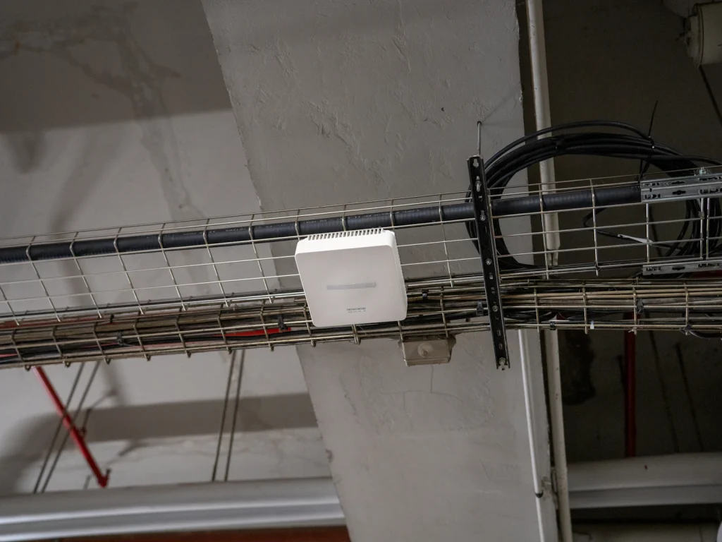
The numbers from TIA-569, BICSI and NEMA VE 2
- Fill no more than 50% of the inside cross-section, cable no deeper than 150 mm, and about 25% at handover.
- Wire basket supported at least every 1.5 m (5 ft), with supports on both sides of splices and intersections and at every change of elevation. Toronto Metropolitan University’s cabling standard spells this out.
- Support span no longer than the straight section, so there is one splice per span, placed about a quarter of the span from a support (NEMA VE 2).
- Fittings supported within about 600 mm (2 ft) of each end. Vertical elbows at the top of a run are supported at both ends; at the bottom, at the top end and within 600 mm of the lower end.
- Radiused waterfalls or drop-outs wherever cable drops into racks, so it never bends over a bare rung or wire.
- Tray and runway bonded to the telecom bonding system per ANSI/TIA-607.
Fire separations
A tray route will cross fire separations: corridor walls, shaft walls and floor slabs. Each penetration has to be sealed with a firestop system tested for that wall or floor and that cable load, which in Canada means a system tested to CAN/ULC-S115, and resealed after every add. On data routes we usually stop the tray on each side of a rated wall and pass the cable through sleeves or a firestop pathway device, so new cable can go through without breaking the seal. More on this in our post on cable management and fire safety.
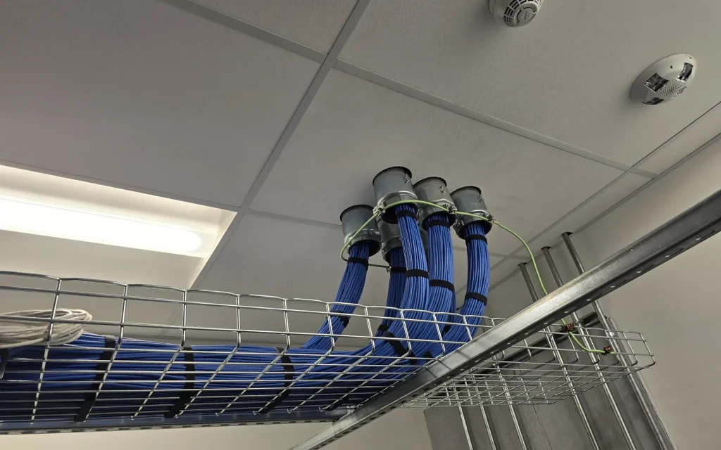
How cable tray is installed
This is the order the work happens in on site. The figures below are the common defaults. Where the manufacturer’s instructions or the project specification differ, they win.
Route, elevation and coordination
Walk the route with the reflected ceiling plan and the mechanical drawings. Tray competes for space with ducts, sprinkler mains, lighting and, in warehouses, racking and sprinkler heads. Sprinkler obstruction rules can push a tray lower or to one side, so settle that before anything is hung. Leave at least 300 mm above the tray to lay cable in, keep it above lay-in ceiling tiles or behind access panels, and plan where each rack, room and device group will be fed from.
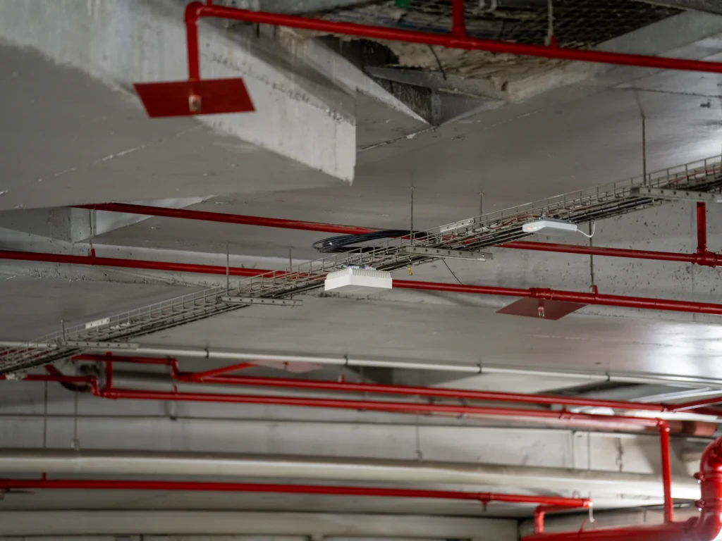
Supports and anchors
Take the support spacing from the manufacturer’s load table for the tray, the load and the span, and never more than 1.5 m on telecom basket. Add supports within about 600 mm of each fitting and on both sides of basket splices. Hang everything from the structure: concrete anchors rated for the load, or beam clamps on steel. Do not drill structural steel without the engineer’s approval, and never hang tray from ceiling grid wires, ductwork, sprinkler pipe or another trade’s supports. Set trapezes level so the tray runs straight, and add seismic bracing where the structural design calls for it.
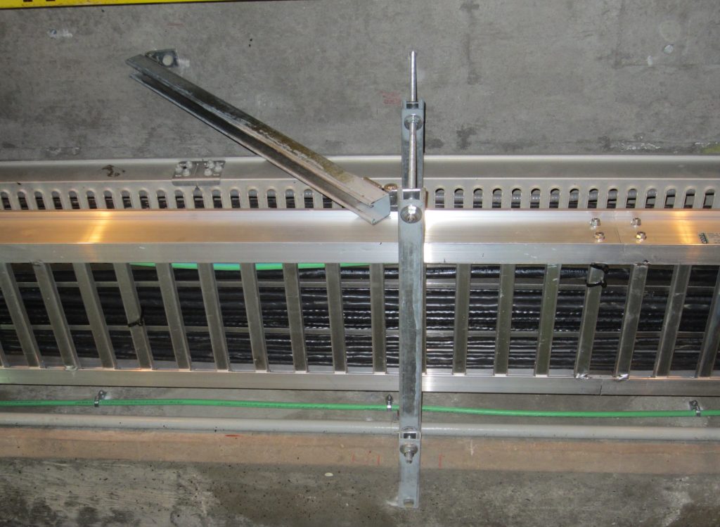

Assembly, cutting and fittings
On ladder and trough, place one splice per span at about the quarter point and torque the splice bolts to the maker’s figure. On wire basket, cut wires with side-cutting bolt cutters so no sharp stubs are left, form bends and tees the way the maker shows, and join them with the maker’s splice hardware. Touch up cut ends of hot-dip galvanized tray with zinc-rich paint. Check every fitting radius against the bend radius of the biggest cable that will use it.
Bonding
Make the tray one continuous bonded path. Wherever it is broken, at a wall, an expansion splice, a hinged splice or a gap left for another service, carry the path across with a bonding jumper unless the hardware is listed for bonding. In telecom rooms, bond the tray and runway to the telecommunications grounding busbar. Use tin-plated lugs and clamps on aluminum.
Drops, transitions and rack entries
Fit a waterfall, drop-out or radius drop at every point where cable leaves the tray. Join conduit to the tray with a proper adapter or clamp rather than leaving the cable to bridge the gap. Over racks, mount runway or basket with rack-top kits, and bring cable down into vertical managers rather than straight onto the patch panels.
Laying and dressing cable
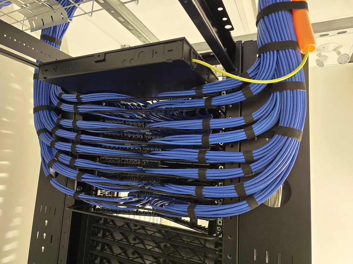
Lay cable in rather than dragging it over rungs and edges. On long or heavy pulls, use rollers and sheaves at bends. Keep systems apart, group cables by destination, and secure bundles with hook-and-loop straps loose enough that the cables can still move. Tight nylon ties deform Cat6A and can cause test failures. On vertical runs, fasten the cable so its weight hangs from the tray, not from the terminations. Keep the pile below 150 mm.
For the cabling side of the job, see our Cat6A cabling page and our article on how poor installation affects network performance.
Labelling and records
Label pathways following ANSI/TIA-606 at regular intervals and at each side of a wall, and keep record drawings showing the tray route, size and fill. A future contractor should be able to tell what a tray is for and how much room is left without climbing a ladder.
Inspection and upkeep
Look over the tray once a year for physical damage, overloading and loose connections. Take abandoned cable out when you can. It uses up capacity and adds fuel to a fire, and it is far easier to remove before new cable is laid on top of it. Our abandoned cable removal service does exactly that.
Expansion joints
Inside a heated building, tray barely moves and expansion joints are rarely needed except on very long runs. Rooftops, parking garages, loading docks and unheated warehouses are different. In Southern Ontario, the swing between a winter night and summer sun on the metal can easily pass 55 °C. ABB’s technical guide gives these maximum distances between expansion joints:
| Temperature swing | Steel | Aluminum | 316 stainless |
|---|---|---|---|
| 28 °C (50 °F) | 78 m (256 ft) | 40 m (130 ft) | 58 m (189 ft) |
| 42 °C (75 °F) | 52 m (171 ft) | 27 m (87 ft) | 38 m (126 ft) |
| 56 °C (100 °F) | 39 m (128 ft) | 20 m (65 ft) | 29 m (95 ft) |
| 70 °C (125 °F) | 31 m (102 ft) | 16 m (52 ft) | 23 m (76 ft) |
| 83 °C (150 °F) | 26 m (85 ft) | 13 m (43 ft) | 19 m (63 ft) |
Expansion splice plates typically allow about 25 mm of movement. Set the gap for the temperature on the day of installation, put a bonding jumper across every expansion joint, and leave a little slack in the cable at each joint so it is not stretched when the tray moves.
Which cable tray for which building
| Setting | Usual tray | Finish | Points to watch |
|---|---|---|---|
| Office ceilings | Wire basket, 50 to 100 mm deep, on corridors; J-hooks to rooms | Electro-zinc or pre-galvanized | 300 mm headroom; reachable above lay-in tiles; after-hours work in occupied floors |
| MDF, IDF and server rooms | Cable runway, with basket for longer runs into the room | Black powder coat or electro-zinc | Rack-top mounting, radius drops, bonding to the grounding busbar |
| Data centres | Basket or single rail over the rows, plus fiber raceway | Powder coat or the owner’s standard | Separate copper and fiber; check the owner’s zinc policy |
| Warehouses and distribution centres | Basket for data; ladder for power | Pre-galvanized; HDG where unheated | Lift access, sprinkler clearance, long spans, expansion in unheated buildings |
| Manufacturing plants | Ladder or trough for power and control; separate basket for data | HDG or aluminum | Distance from motors and VFD cable; protection near moving equipment |
| Parking garages, loading docks, rooftops | Ladder or channel, with covers outdoors | HDG, aluminum, 316 stainless or FRP | Road salt, sun-rated cable, peaked covers, expansion joints |
| Food, beverage and pharmaceutical | Basket or ladder | 316 stainless steel | Cleanability; avoid solid bottoms that trap debris |
| Chemical plants and wastewater | Ladder or trough | Fiberglass (vinyl ester) | FRP load tables; UV exposure outdoors |
| Schools and hospitals | Basket on corridors with branches to rooms | Electro-zinc or pre-galvanized | Many fire separations to firestop; seismic restraint where the design requires it |
Corridor-and-branch layouts like these come up in most of our office and warehouse work. For the room counts and drop planning behind them, see planning a new office network and planning a server room or IDF closet.

Reading part numbers and ordering cable tray
Tray part numbers look cryptic, but most of them encode the same few things. Four examples from a distributor listing:
Cablofil CF105/300EZ
CF105 series wire basket with 105 mm (about 4 in) sides, 300 mm (12 in) wide, EZ electro-zinc finish, 3 m (10 ft) long. The CF54 series is the 2 in deep version.
Eaton B-Line FT6X24X10 BLE
FlexTray wire basket, 6 in deep, 24 in wide, 10 ft nominal length (118 in), with the BLE finish code at the end.
Eaton B-Line 46A09-36-144
46 series ladder tray in aluminum (A), 9 in rung spacing (09), 36 in wide, 144 in (12 ft) long.
Chatsworth 10250-712
Universal cable runway, 12 in wide, 1.5 in high, just under 10 ft long, in black. The same runway is 10250-706 at 6 in wide and 10250-724 at 24 in.
On the spec or the purchase order, pin down these items:
- Tray type and manufacturer’s series
- Material and finish
- Inside width and usable loading depth, not just side rail height
- Straight section length, at least as long as the support span
- Design load (kg/m or lb/ft) and support span, or the CSA or NEMA load class
- Rung spacing for ladder tray
- Fitting radius and a counted list of fittings
- Splice type, including expansion splices where needed
- Supports: type, rod size, anchors or beam clamps, hold-downs
- Covers, dividers, drop-outs and waterfalls
- Bonding hardware
- CSA C22.2 No. 126.1 certification marking where the tray serves as a raceway
Mistakes we see on cable tray jobs
- Filling to the top of the side rail. The bottom cables get crushed, the 150 mm pile limit is gone, and there is no room for the next project.
- Hanging tray from the ceiling grid, ductwork or sprinkler pipe. It has to hang from the structure.
- Supports too far apart on basket, and none near fittings. The tray sags, and Cat6A bundles take a permanent set at every low point.
- Two splices in one span, or a splice at mid-span on ladder tray. That is where the bending load is highest.
- Power and data in one tray with no divider. Or data tray running alongside VFD output cable for 50 m.
- No waterfalls. Cable folded over a bare wire or rung where it drops into a rack.
- Nylon ties cinched tight on Cat6A. Use hook-and-loop straps, loose enough that the cables can move.
- Tray running straight through a rated wall with an unsealed gap or a can of foam instead of a tested firestop system.
- Breaks in the bonding. Expansion splices with no jumper, gaps at walls, or bare copper lugs on aluminum tray.
- Tray tight against the deck. With no room above it, nobody can lay cable in.
- Dead cable left in place. It takes up capacity and adds fuel load.
- Using tray as a shelf. Ladders leaned on it, other services hung from it, spare cable boxes stored in it.

Planning a cable tray route?
Cablify designs and installs wire basket, ladder, trough and runway tray across Toronto and the GTA, sized from the real cable count and installed by our own technicians together with the copper and fiber that go in it. Where a tray will carry power, that electrical work is done by an ECRA/ESA Licensed Electrical Contractor. Send us a floor plan, a few ceiling photos and a cable count, and we will tell you what we would use and why.
FAQ
What are the main types of cable tray?
The main types are ladder, ventilated trough, solid bottom, channel, wire mesh (basket) and single rail tray. Inside network rooms, cable runway (also called ladder rack) does the same job over the racks, and data centres often add a plastic fiber raceway for patching. Wire basket carries most structured cabling in commercial buildings, and ladder tray carries most power and long backbone runs.
What are the components of a cable tray system?
A complete system has straight sections; fittings such as horizontal elbows, tees, crosses, wyes, reducers and vertical inside and outside elbows; splice plates and splice hardware; supports such as trapeze hangers, centre hangers, wall brackets and hold-down clamps; accessories such as covers, dividers, drop-outs and waterfalls, end plates and conduit adapters; and bonding hardware such as bonding jumpers, grounding clamps and lugs.
What is the difference between cable tray and cable runway?
Cable runway, also sold as ladder rack, is a light ladder made of tubular steel stringers about 38 mm (1.5 in) high. It is designed for telecom rooms, where it bolts to the tops of racks and carries cable over them and down into them. Cable tray is the broader family used along corridors, ceilings and plant floors, and is built and load-rated for longer spans between supports.
How full can a cable tray be?
For telecommunications cabling, ANSI/TIA-569 limits fill to 50% of the tray’s inside cross-section and limits the cable pile to 150 mm (6 in) deep. Because round cables leave gaps, a tray at 50% calculated fill already looks full, so designers aim for about 25% at handover to leave room for future cable.
How far apart should cable tray supports be?
Support spacing comes from the tray’s rated load at a given span, which the Canadian Electrical Code requires you to stay within. For telecom wire basket, TIA-569 calls for supports at least every 1.5 m (5 ft). NEMA VE 2 adds that the span should not exceed the straight section length, splices should sit about a quarter of the span from a support, and fittings should be supported within about 600 mm (2 ft) of each end.
Does cable tray need to be bonded to ground?
Yes. Metal tray must form a continuous bonded path, with bonding jumpers across expansion splices, gaps and breaks at walls. In telecom rooms, tray and runway are bonded to the telecommunications grounding busbar following ANSI/TIA-607. Use tin-plated connectors on aluminum tray, because bare copper bolted to aluminum corrodes.
Can power and data cables share a cable tray in Canada?
Only with separation. The Canadian Electrical Code allows conductors of different systems in the same raceway when they are all insulated for the highest voltage present, when one system is in continuous armoured or metal-sheathed cable, or when a sheet steel barrier at least 1.3 mm thick separates them. Section 60 adds its own separation rules for communication cables. In practice, a solid metal divider or a separate tray is the clean answer.
Is cable tray a raceway under the Canadian Electrical Code?
Yes. The Canadian Electrical Code defines cable tray as a raceway made of troughing and fittings that lets insulated conductors and cables be installed or removed after the tray is in place, and Rules 12-2200 to 12-2210 cover its installation. The US National Electrical Code treats cable tray as a support system rather than a raceway, so US guidance does not always carry over.
Which cable tray is best for network cabling?
Wire mesh basket tray is the usual choice for Cat6, Cat6A and fiber in offices, telecom rooms and data centres, because it is light, cut and shaped on site, and open for adding cable. Inside the network room, cable runway carries cable over the racks. Ladder tray suits long, heavy backbone runs, with 150 mm rung spacing so small cables are not bent over each rung.
What finish should I choose for cable tray?
Electro-zinc or pre-galvanized steel is fine in dry indoor spaces such as offices and telecom rooms. Use hot-dip galvanized steel, aluminum or 316 stainless steel outdoors, in parking garages and loading docks where road salt reaches the tray, and in wet areas. Use stainless steel in food and pharmaceutical washdown areas, fiberglass in corrosive chemical areas, and powder-coated tray where appearance matters or the owner’s standard calls for it.
Can cable tray pass through a fire-rated wall?
The opening must be sealed with a firestop system tested for that wall and that cable load, which in Canada means a system tested to CAN/ULC-S115. On data routes the tray usually stops on each side of the rated wall, and cables pass through sleeves or a firestop pathway device, so cable can be added later without breaking the seal.
Standards and references used in this guide
- CSA C22.1:24, Canadian Electrical Code, Part I, and the 2024 Ontario Electrical Safety Code (29th edition)
- CSA C22.2 No. 126.1-17 / NEMA VE 1, Metal cable tray systems
- CAN/CSA C22.2 No. 126.2, Nonmetallic cable tray systems, and NEMA FG 1
- NEMA VE 2-2013, Cable Tray Installation Guidelines
- ANSI/TIA-569-E, Telecommunications Pathways and Spaces; ANSI/TIA-607-D, Bonding and Grounding; ANSI/TIA-606, Administration
- BICSI Telecommunications Distribution Methods Manual and Information Technology Systems Installation Methods Manual
- ABB (Thomas & Betts) Cable Tray Technical Guide
- Toronto Metropolitan University, Section 27 05 36 cabling standard; University of Saskatchewan master specification 26 05 36
- Manufacturer and distributor data from Graybar, Eaton B-Line, Legrand Cablofil, Chatsworth Products and Hubbell