
How Ethernet Cable Shielding Works
Every ethernet cable carries data as differential electrical signals on twisted wire pairs. The twisting itself provides the first line of defence against interference — equal and opposite signals cancel out noise that hits both wires equally. But in high-interference environments, twisting alone isn’t enough. That’s where shielding comes in.
Shielding is a conductive layer — foil, braided wire, or both — placed around the twisted pairs to intercept, absorb, and redirect electromagnetic energy before it can corrupt the signal.
The Two Types of Interference Shielding Addresses
- EMI (Electromagnetic Interference): External noise from motors, generators, fluorescent lighting, HVAC systems, MRI machines, industrial equipment, and radio transmitters. EMI induces voltage in nearby cables, corrupting the signal. Shielding blocks this external noise from reaching the conductors.
- Crosstalk (NEXT/FEXT): Noise that bleeds between pairs within the same cable bundle. At high frequencies (10Gbps+), pair-to-pair crosstalk becomes the dominant performance limiter. Individual pair shielding eliminates this by isolating each pair in its own Faraday cage.
A shielding layer acts as a Faraday cage — an enclosure of conductive material that distributes electromagnetic charges around its exterior, cancelling the field inside. For shielding to work, the cage must be continuous and properly grounded. A broken or ungrounded shield is often worse than no shield at all, as it can act as an antenna and amplify interference.
How the Shield Redirects Energy
When an electromagnetic field encounters the shield, three things happen simultaneously: part of the energy is reflected away from the cable, part is absorbed and converted to heat in the conductive layer, and the remainder passes through — attenuated. The effectiveness of this process depends on the shield material, thickness, coverage percentage, and critically, whether the drain wire is properly terminated at both ends.
The Drain Wire
All shielded cables include a drain wire — an uninsulated conductor that runs in contact with the foil shield along the full length of the cable. The drain wire provides the continuous electrical connection needed to ground the shield. Without a properly terminated drain wire, the shield cannot function. In installations where the drain wire is left unconnected at one or both ends, the cable may fail channel certification even though the physical shielding is intact.
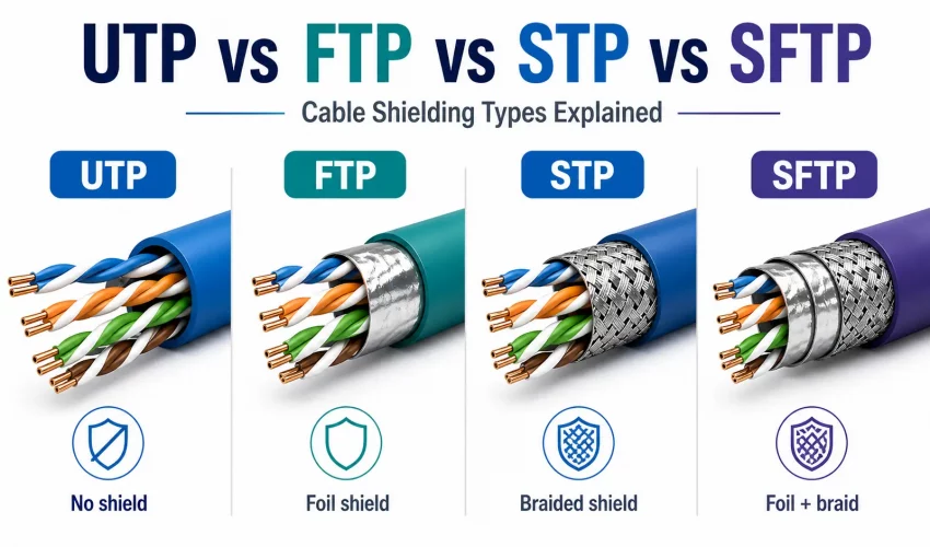
The ISO/IEC 11801 Naming System Explained
The cable shielding naming system is frequently misused in the field. Terms like “STP” and “FTP” are often used interchangeably — incorrectly. The definitive reference is the ISO/IEC 11801 standard, which defines a two-part naming convention that precisely describes the shielding on both the overall cable and the individual pairs.
| ISO 11801 Code | Common Name | Overall Shield | Per-Pair Shield | Typical Use |
|---|---|---|---|---|
| U/UTP | UTP | None | None | Office, home, standard LAN |
| F/UTP | FTP / ScTP | Overall foil | None | Light industrial, some offices |
| U/FTP | STP (loose usage) | None | Foil per pair | 10GBase-T, data centres |
| F/FTP | FTP / FFTP | Overall foil | Foil per pair | High-interference industrial |
| S/FTP | SFTP / PiMF | Overall braid | Foil per pair | Severe EMI, Cat7/Cat8 |
| SF/FTP | SFTP (full) | Braid + foil | Foil per pair | Extreme EMI, Cat8 data centres |
“STP” is one of the most misused terms in networking. In ISO 11801, STP strictly means a cable with a braided shield per pair and no overall shield (U/STP) — a configuration almost never used in practice. What most installers call “STP” is actually S/FTP or F/UTP. When ordering cable, always specify the ISO code (e.g., U/FTP Cat6A) rather than relying on common names to avoid receiving the wrong product.
UTP — Unshielded Twisted Pair (U/UTP)
UTP is the global standard for ethernet cabling in commercial and residential environments. It relies entirely on the physics of twisted pairs — the twist rate varies between pairs within the cable to differentiate their resonant frequencies and minimise crosstalk. No metallic shielding layer is present.
Why UTP Works in Most Buildings
Modern commercial buildings are surprisingly clean electromagnetic environments. Steel framing, concrete structure, and distance from industrial equipment keep ambient EMI levels low enough that UTP’s inherent crosstalk rejection handles the job. The vast majority of corporate office networks, school networks, retail installations, and residential structured cabling use U/UTP Cat6 or Cat6A — and perform perfectly for decades.
Use UTP when: the building has no significant EMI sources (motors, generators, fluorescent lighting on the same circuit runs, RF transmitters), cable runs don’t pass near electrical panels or HVAC equipment, and the environment is standard office or commercial space. This covers approximately 80% of commercial ethernet installations.
UTP Advantages
- Lowest cost per metre — typically 20–40% cheaper than equivalent shielded cable
- Lightest and most flexible — easier to pull through conduit and route in tight spaces
- No grounding infrastructure required — eliminates a significant installation complexity
- No ground loop risk — improper grounding of shielded cable can introduce more noise than it eliminates
- Compatible with all standard RJ45 termination equipment and patch panels
- Easier field termination — no drain wire to manage, less jacket to strip
UTP Limitations
- No protection against external EMI fields — vulnerable near motors, generators, VFDs
- Not suitable for outdoor or direct-burial installation without additional protection
- Cannot be used in environments requiring EMC compliance for sensitive equipment
FTP / F/UTP — Overall Foil Shield
F/UTP (commonly called FTP or ScTP — Screened Twisted Pair) adds a single metallic foil layer wrapped around all four pairs together, beneath the outer jacket. The pairs themselves remain unshielded. A drain wire runs in contact with the foil along the cable’s full length.
What the Overall Foil Protects Against
The foil layer is highly effective at blocking high-frequency EMI — radio frequency interference (RFI) from transmitters, microwave equipment, and other RF sources. It provides moderate protection against lower-frequency EMI from motors and fluorescent lighting. What it does not address is pair-to-pair crosstalk — because the pairs inside the shield remain unshielded relative to each other.
F/UTP must be grounded at both ends to function correctly. However, grounding at both ends in buildings with different ground potential creates a ground loop — a circulating current in the shield that introduces hum and noise into the very signal it’s supposed to protect. Proper installation requires either a single-point ground or equipment with ground loop isolation. This is the most common cause of FTP installation failures in the field.
FTP Typical Applications
- Hospital environments with sensitive medical equipment
- Light manufacturing areas where motors run near cable trays
- Environments near large fluorescent or LED driver arrays
- Outdoor runs in conduit where RF ingress is a concern
- Government or military facilities requiring EMC compliance
U/FTP — Individually Foil-Shielded Pairs (often called STP)
U/FTP has no overall shield, but wraps each of the four pairs in its own individual foil layer. This configuration directly targets pair-to-pair crosstalk (NEXT and FEXT) by isolating each pair in its own Faraday cage. It is the dominant configuration for Cat6A 10GbE and higher-performance applications.
Why U/FTP Dominates High-Speed Installations
At 10Gbps (Cat6A) and above, alien crosstalk — interference between cables in adjacent bundles — becomes the primary performance constraint. Individual pair shielding eliminates the internal crosstalk component entirely, allowing the cable to meet channel performance specifications over longer runs and in larger bundles without the aggressive bundle size restrictions imposed on U/UTP Cat6A.
U/FTP Cat6A cables are also typically smaller in diameter than U/UTP Cat6A (which uses a thick inner separator to manage crosstalk), making them significantly easier to pull in congested pathways and more conduit-efficient.
In structured cabling for data centres, U/FTP Cat6A or S/FTP Cat7 is the professional recommendation — not because EMI is necessarily a concern, but because individual pair shielding eliminates alien crosstalk and enables higher port densities in patch panels and cable trays without performance degradation.
S/FTP & SF/FTP — Braid + Foil (SFTP)
S/FTP combines an overall braided shield with individual foil shielding on each pair. SF/FTP adds an additional overall foil layer beneath the braid. These are the highest-performance shielding configurations, used in severe EMI environments, Cat7, Cat7A, and Cat8 cable specifications.
The Braid Shield Advantage
Where foil shields are thin and effective against high-frequency interference, braided shields add low-frequency EMI rejection, mechanical durability, and significantly higher coverage percentages (typically 85–98% vs. foil’s near-100% for HF but lower LF effectiveness). The combination of braid + per-pair foil delivers attenuation across the full frequency spectrum — from 50Hz power-frequency hum to multi-GHz RF.
When SFTP is Required
- Within or adjacent to MRI suites — the RF pulses and gradient fields are intense enough to corrupt any unshielded cable
- Industrial factory floors with large VFDs (Variable Frequency Drives), CNC machines, or arc welders
- Broadcasting facilities with high-power transmitters in the building
- Military and government secure facilities with strict TEMPEST/EMC requirements
- Cable runs within or adjacent to elevator shafts (strong motor fields)
- Cat7 and Cat8 specifications — both mandate S/FTP or SF/FTP construction by design
The Termination Challenge
SFTP cable requires shielded RJ45 connectors (or GG45/TERA for Cat7/7A) with proper 360° shield termination. Standard unshielded keystones and patch panels cannot be used. The braided drain must be terminated with a full-circumference connection to the connector shell — pigtail grounding (wrapping the drain wire around a pin) reduces shield effectiveness by up to 90% at high frequencies and is a code violation in most jurisdictions.
Full Comparison: All 4 Shielding Types
| Attribute | UTP (U/UTP) | FTP (F/UTP) | STP (U/FTP) | SFTP (S/FTP) |
|---|---|---|---|---|
| ISO Code | U/UTP | F/UTP | U/FTP | S/FTP or SF/FTP |
| Overall Shield | None | Aluminium foil | None | Copper braid (+ foil) |
| Per-Pair Shield | None | None | Foil per pair | Foil per pair |
| EMI Protection | Basic (twist only) | Moderate (HF EMI) | Good (crosstalk + EMI) | Maximum (full spectrum) |
| Crosstalk Rejection | Twist-based only | Twist-based only | Excellent (per-pair foil) | Excellent (per-pair foil) |
| Grounding Required | No | Yes — both ends | Yes — both ends | Yes — critical, both ends |
| Ground Loop Risk | None | Yes — if improperly grounded | Yes — if improperly grounded | Yes — if improperly grounded |
| Connector Type | Standard RJ45 | Shielded RJ45 | Shielded RJ45 | Shielded RJ45 / GG45 |
| Cable Diameter (Cat6A) | 7–8mm (large) | 6–7mm | 6–6.5mm (slim) | 7–9mm (large) |
| Weight | Lightest | Light | Moderate | Heaviest |
| Flexibility | Best | Good | Good | Reduced |
| Relative Cost | 1x (baseline) | 1.3–1.5x | 1.4–1.7x | 2–3x |
| Best For | Standard offices, homes | Light industrial, hospitals | Data centres, 10GbE | Severe EMI, Cat7/8 |
Which Cable Do You Need? Environment Guide
Interactive Shielding Recommendation Tool
Grounding: The Critical Requirement Nobody Mentions
Shielded cable that isn’t properly grounded doesn’t just fail to protect — it can actively make interference worse. The shield becomes an antenna, picking up EMI and capacitively coupling it into the pairs it was meant to protect.
The Single-Point vs. Both-Ends Grounding Debate
There are two valid grounding approaches, and choosing the wrong one for your installation is the single most common cause of shielded cable failures:
- Single-point grounding (one end only): Eliminates ground loop risk by breaking the circuit between the two ground references. Used when the two ends of the cable are at different buildings or different electrical systems. The shield still provides protection against high-frequency EMI through capacitive coupling, but is less effective at low frequencies.
- Both-ends grounding: Provides maximum shield effectiveness across the full frequency spectrum. Required by TIA-568 for most commercial installations. Only works correctly when both ends are at the same ground potential — meaning the same electrical distribution system. If there is any ground potential difference, a circulating current flows through the shield and introduces hum.
If you measure AC voltage between the shield ground at the patch panel and the shield ground at the outlet, any reading above 1V indicates a ground potential difference that will cause ground loop hum. This is common in older buildings with poor bonding, in buildings with multiple electrical services, and in any installation spanning separate buildings. Test before committing to a both-ends ground configuration.
Proper Shield Termination at the Connector
The shield must make 360° contact with the connector’s metallic shell. This means:
- Using shielded RJ45 plugs and keystone jacks with a metallic housing
- Folding the foil back over the cable jacket and clamping it under the connector’s shield clamp — not wrapping the drain wire around a pin
- For braided shields: the braid must be folded back and captured in the connector’s clamp, not trimmed away
- Shielded patch panels must be bonded to the rack, which must be bonded to the building ground bus
Grounding the Rack Infrastructure
For shielded cabling to function as a system, the entire infrastructure must be grounded: shielded patch panels connect to shielded patch cords, which connect to shielded switch ports. A single unshielded component in the chain breaks the Faraday cage and eliminates the protection.
7 Common Shielding Mistakes
Mistake #1: Using Shielded Cable Without Grounding It
This is the most common and most damaging mistake. Ungrounded shielded cable acts as an antenna, often performing worse than UTP in the same environment. Every shielded installation requires a verified ground path from shield to earth at the correct termination points.
Mistake #2: Pigtail Grounding Instead of 360° Termination
Wrapping the drain wire around a connector pin (pigtail ground) creates a high-impedance connection that is essentially useless above a few MHz. At 100MHz — the Cat5e frequency ceiling — a pigtail ground has near-zero effectiveness. All shielded connectors must use circumferential clamp termination.
Mistake #3: Mixing Shielded Cable with Unshielded Connectors
Using F/UTP cable terminated into standard unshielded keystones eliminates the shield at every termination point. The shield exists only in the cable run itself but is not connected to anything. This provides essentially no benefit over UTP.
Mistake #4: Specifying Shielded Cable in Clean Environments
Shielded cable in a clean office environment adds 20–40% material cost, requires more time to terminate correctly, increases ground loop risk, and provides zero performance benefit over UTP. Specify shielding only where EMI measurement or environmental assessment confirms a need.
Mistake #5: Not Testing for Ground Loops After Installation
A ground loop manifests as a 50/60Hz hum on audio circuits and as degraded BER on ethernet links. After any shielded installation, verify ground continuity and measure ground potential difference between termination points before commissioning. A time-domain reflectometer (TDR) test alone will not reveal ground loop issues.
Mistake #6: Using the Wrong Category for the Application
Specifying S/FTP Cat7 for an office environment is common over-engineering. The shielded connectors (GG45 or TERA) required for Cat7 are expensive, fragile, and require specialist termination. For most installations requiring shielded cable, F/UTP or U/FTP Cat6A with standard shielded RJ45 is technically sufficient and far more practical.
Mistake #7: Not Maintaining the Shield Through Conduit Transitions
When shielded cable transitions through metallic conduit fittings, the conduit must be properly bonded to the cable’s shield ground. An interruption in the grounding path at a conduit entry point — such as a plastic bushing inserted to protect the cable jacket — can break the ground circuit if the plastic is not bridged by a separate bonding conductor.
Frequently Asked Questions
Need Help Specifying the Right Cable for Your Project?
Cablify designs and installs ANSI/TIA-568 and ISO 11801 compliant structured cabling systems across Toronto and the GTA. UTP, FTP, and S/FTP Cat6A — full channel certification included.