
Picture this: your team is in the middle of an important video call, file transfers are crawling, and your VoIP phones keep dropping. Meanwhile, your IT manager is staring at a network monitor wondering where all the bandwidth went. The answer? Your 24 IP security cameras are streaming 1080p footage 24 hours a day — directly onto the same network your staff uses to run the business.
This is one of the most common and costly networking mistakes we see in commercial buildings across the GTA. IP cameras are powerful, affordable, and easy to install — but almost no one tells you that mixing surveillance traffic with corporate data traffic on the same flat network is a recipe for poor performance, security vulnerabilities, and escalating troubleshooting costs.
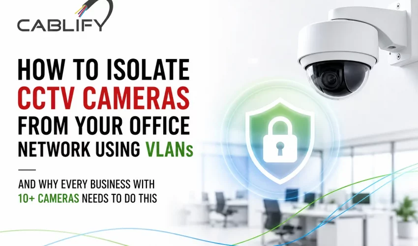
The fix is a CCTV VLAN: a dedicated, logically isolated segment of your network where your cameras and NVR live completely separate from everything else. In this guide, we’ll explain what a CCTV VLAN is, why it matters, and walk you through exactly how to set one up — step by step.
Why IP Cameras Don’t Belong on Your Main Office Network
When your office network was first set up, it was probably designed around workstations, printers, and maybe a server or two. Adding 10, 20, or 30 IP cameras to that same network without any segmentation creates three serious problems.
1. Bandwidth Saturation
A single 1080p IP camera streaming continuously at 2 Mbps doesn’t sound like much. But multiply that by 20 cameras and you’re pushing 40 Mbps of constant background traffic on a network that your staff is also using for Microsoft Teams calls, cloud backups, and file sharing. At 4K resolution, that number climbs past 80 Mbps. On a 100 Mbps uplink to your core switch, surveillance traffic can consume the majority of your available capacity before the business day even starts.
2. Security Exposure
IP cameras are notoriously among the least secure devices on any network. Most run embedded firmware that rarely gets updated, many ship with default credentials that never get changed, and a growing number communicate with manufacturer cloud servers in China and other jurisdictions with unclear data handling practices. When these cameras sit on your corporate LAN, a compromised camera becomes a foothold inside your network — with direct access to servers, shared drives, and workstations. VLAN isolation removes that risk entirely.
3. Broadcast Storm Risk
Cameras that malfunction or are misconfigured can trigger broadcast storms — flooding the network with traffic that every device has to process. On a flat, unsegmented network, a single misbehaving camera can take down your entire office. On an isolated VLAN, the storm stays contained within the camera segment and your business operations continue unaffected.
What Is a VLAN? (Plain-Language Explanation)
A VLAN — Virtual Local Area Network — is a way of dividing a single physical network switch into multiple logically separate networks. Think of it like having two completely different buildings inside one physical office, with a security guard at the door between them controlling exactly who can pass through and when.
Devices on VLAN 10 (your corporate network) cannot see or talk to devices on VLAN 20 (your CCTV network) unless you explicitly create a rule allowing that communication. From a traffic and security standpoint, they behave like entirely separate networks — even though they share the same physical switches and cabling infrastructure.
VLANs are configured on managed switches using VLAN IDs (numbers between 1 and 4094). Common CCTV VLAN IDs used in commercial deployments include VLAN 30, 40, or 50 — keeping them clearly separate from the default VLAN 1 (which should never be used for production traffic).
What You Need Before You Start
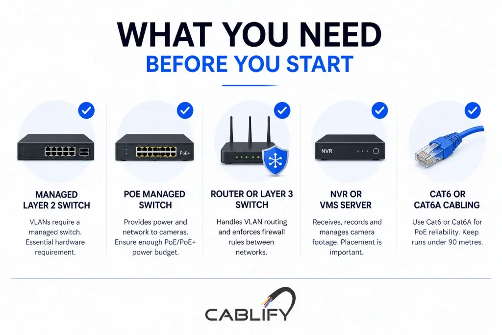
VLAN isolation requires managed switching. Here’s what your infrastructure needs to include before you can implement this properly:
- A managed Layer 2 switch — Unmanaged switches have no VLAN capability whatsoever. You need a managed switch from a brand like Cisco (CBS350 series), Ubiquiti UniFi (USW-24-PoE), NETGEAR (GS724TP), or TP-Link Omada (TL-SG3428). This is the non-negotiable hardware requirement.
- A PoE managed switch for cameras — In most commercial CCTV deployments, cameras are powered via Power over Ethernet. Your managed switch must support PoE or PoE+ (802.3af or 802.3at) with sufficient power budget for all connected cameras. Calculate 15–25W per camera for standard IP cameras, 25–30W for PTZ cameras.
- A router or Layer 3 switch with VLAN routing capability — This is what enforces the firewall rules between VLANs and controls which traffic is allowed to cross from the CCTV segment to the corporate segment (or the internet).
- An NVR (Network Video Recorder) or VMS server — This is the device that receives, records, and manages footage from your cameras. Its placement within the VLAN design is critical, as discussed below.
- Cat6 or Cat6A cabling — For PoE camera runs, always use Cat6 or Cat6A. Cat5e is technically capable but leaves no headroom for PoE+ power delivery over longer runs. Keep all camera cable runs under 90 metres.
Step-by-Step: How to Set Up a CCTV VLAN for Your Business
The following walkthrough covers the logical process for any managed switch environment. Exact menu paths vary slightly between Cisco, Ubiquiti, NETGEAR, and TP-Link, but the underlying steps are identical across all platforms.
Step 1: Plan Your VLAN ID and IP Address Scheme
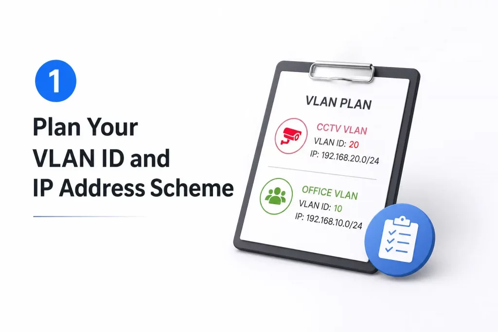
Before touching any switch configuration, document your design on paper. Good VLAN planning prevents mistakes that are painful to undo after cameras are installed.
A typical commercial deployment might look like this:
- VLAN 10 — Corporate LAN: 192.168.10.0/24
- VLAN 20 — Guest Wi-Fi: 192.168.20.0/24
- VLAN 30 — CCTV / Surveillance: 192.168.30.0/24
- VLAN 40 — VoIP phones: 192.168.40.0/24
Assign your cameras static IP addresses within the CCTV VLAN subnet (e.g., 192.168.30.10 through 192.168.30.50). Static IPs on cameras are strongly recommended over DHCP — cameras moving IP addresses causes NVR recording gaps that are difficult to diagnose.
Step 2: Create the CCTV VLAN on Your Managed Switch
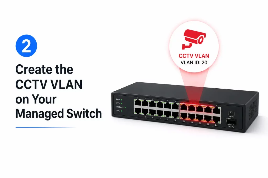
Log into your managed switch’s administration interface and create a new VLAN entry with your chosen VLAN ID (e.g., VLAN 30) and a descriptive name such as “CCTV-Surveillance.” Save this to the VLAN database. At this stage, the VLAN exists but no ports are assigned to it yet.
Step 3: Configure Camera Ports as Access Ports
Each physical port on your switch that a camera connects to must be configured as an access port assigned to VLAN 30. An access port belongs to exactly one VLAN and strips VLAN tags before forwarding traffic to the connected device (the camera doesn’t need to know anything about VLANs — it just sees a network it can communicate on).
In Cisco CLI, this looks like:
interface FastEthernet0/3
 switchport mode access
 switchport access vlan 30
In Ubiquiti UniFi, you assign the port profile “CCTV” to each camera port through the switch port settings panel. In TP-Link Omada, you set Port VLAN to PVID 30 on each camera port.
Step 4: Configure the Trunk Port Toward Your Router or Core Switch
The uplink port connecting your CCTV switch to your core switch or router must be a trunk port — a port that carries traffic from multiple VLANs simultaneously using 802.1Q VLAN tagging. Configure this uplink to allow both your corporate VLAN and your CCTV VLAN to pass through.
interface GigabitEthernet0/1
 switchport mode trunk
 switchport trunk allowed vlan 10,30
If your cameras are on a dedicated PoE switch that connects upward to a core switch, that inter-switch link is your trunk. Every VLAN that needs to travel between switches must be explicitly allowed on the trunk — VLANs not listed are blocked by default.
Step 5: Place Your NVR on the CCTV VLAN
This is where many installers make a critical error: they put the NVR on the corporate LAN (VLAN 10) and the cameras on the CCTV VLAN (VLAN 30), then wonder why the NVR can’t pull footage. For cameras and NVR to communicate, they need to be on the same VLAN — or you need an explicit inter-VLAN routing rule permitting NVR-to-camera traffic.
The cleanest architecture for most commercial deployments is to place the NVR on VLAN 30 alongside the cameras. The NVR records directly from cameras on the same VLAN, and only NVR management traffic (port 8000, 8080, or RTSP) is allowed to cross from the corporate LAN into the CCTV VLAN so that authorised staff can view footage.
Step 6: Configure Firewall Rules to Block Cross-VLAN Traffic
VLANs alone provide Layer 2 isolation — devices on different VLANs cannot communicate directly. But if your router or Layer 3 switch is performing inter-VLAN routing, traffic can potentially cross between VLANs at Layer 3 unless firewall rules explicitly block it.
The rule set you need for CCTV isolation is straightforward:
- Block all traffic from VLAN 30 to VLAN 10 — cameras should never initiate connections to your corporate network.
- Block all traffic from VLAN 30 to the internet — unless your cameras absolutely require cloud connectivity (which most enterprise IP cameras do not). Blocking outbound internet from the CCTV VLAN prevents camera firmware from phoning home to manufacturer servers.
- Allow VLAN 10 to reach NVR management ports on VLAN 30 — this lets authorised staff access live feeds and recordings from their workstations.
- Allow NTP traffic from VLAN 30 — cameras and NVRs need accurate time synchronisation. Allow UDP port 123 outbound from the CCTV VLAN to your NTP server or an internal time source.
In Ubiquiti UniFi, this is done through Traffic Rules or the Firewall Rules panel under LAN In. In Cisco IOS, you apply ACLs on the VLAN interface. In TP-Link Omada, you configure ACL rules between the CCTV and LAN networks.
Step 7: Test and Verify Isolation
After configuration, always verify that your VLAN isolation is actually working — not just assumed to be working. From a workstation on VLAN 10, try to ping a camera IP on VLAN 30. If the firewall rules are correct, the ping should fail. Then confirm you can still reach the NVR management interface from VLAN 10. Then verify from a camera IP that you cannot ping any device on VLAN 10.
Document every test result. This documentation matters for compliance, insurance, and future troubleshooting.
Add QoS to Prioritise Camera Traffic Within the CCTV VLAN
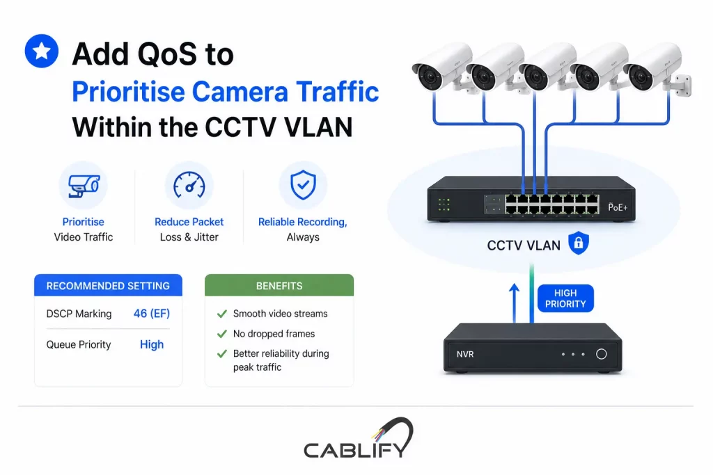
VLAN isolation solves the bandwidth competition problem between cameras and corporate traffic. But within the CCTV VLAN itself — particularly in large deployments with 20 or more cameras — Quality of Service (QoS) ensures that video streams reach the NVR without packet loss or jitter, even during periods of peak traffic.
On your managed PoE switch, configure DSCP marking for camera traffic to prioritise video streams over any management traffic on the same VLAN. Most commercial IP cameras support DSCP marking in their network configuration. Set camera video traffic to DSCP 46 (Expedited Forwarding) and configure your switch’s QoS queuing to honour these markings.
This is particularly important for high-camera-count deployments where multiple cameras share an uplink — for example, 12 cameras feeding through a 1 Gbps uplink to your NVR. Without QoS, burst traffic from motion events on multiple cameras can cause brief queuing that results in dropped frames and recording gaps.
Physical Isolation vs. VLAN Isolation: Which Is Right for Your Business?
Some commercial deployments — particularly those with strict security requirements such as financial institutions, data centres, and government facilities — opt for physical network isolation rather than logical VLAN isolation. This means deploying a completely separate physical switch, separate cabling infrastructure, and a separate NVR with no connection to the corporate network whatsoever.
Physical isolation is more expensive (it essentially doubles your switching infrastructure) but is provably more secure. There is no risk of VLAN misconfiguration, no inter-VLAN routing rule that could accidentally allow traffic through, and no shared physical medium between corporate and surveillance networks.
For most commercial deployments with 10–50 cameras, VLAN isolation on a quality managed switch provides an excellent balance of security, cost, and manageability. Physical isolation becomes worth the investment when your compliance obligations or threat model require it.
Common Mistakes That Defeat VLAN Isolation (And How to Avoid Them)
- Leaving cameras on the native VLAN (VLAN 1): VLAN 1 is the default VLAN on all managed switches and is often not properly secured. Never use VLAN 1 for any production traffic, including cameras.
- Using an unmanaged PoE switch for cameras connected to a managed core switch: Traffic entering through an unmanaged switch arrives untagged on whatever VLAN the access port is configured for. This can work — but only if you understand exactly how your upstream managed switch handles it. Mixing managed and unmanaged switches in CCTV deployments is a source of hard-to-diagnose failures.
- Forgetting to restrict outbound internet access from the CCTV VLAN: VLAN isolation protects your corporate network from cameras. Blocking outbound internet protects your camera footage from leaving your premises. Both rules are needed.
- Skipping the verification step: Assuming VLANs are working without testing is how security misconfiguration stays hidden for months. Always test isolation before signing off on an installation.
- Not documenting the VLAN design: Three months after installation, someone adds a new camera, plugs it into a corporate LAN port, and wonders why the NVR doesn’t pick it up. A documented VLAN map and port assignment sheet prevents this.
Frequently Asked Questions
Do I need a managed switch just for CCTV VLAN isolation?
Yes. There is no way to implement VLANs on an unmanaged switch — they have no VLAN configuration capability. If your current CCTV installation uses an unmanaged PoE switch, you will need to replace it with a managed switch to implement isolation. This is one of the most common infrastructure upgrades we perform for businesses that have grown their camera count beyond 5–10 units.
Can I use a Cisco Catalyst switch for CCTV VLANs?
Absolutely. Cisco Catalyst switches — including the popular CBS350 series designed for small and medium businesses — are excellent choices for CCTV VLAN deployments. They offer robust VLAN support, strong PoE power budgets, and detailed per-port power monitoring that is invaluable for managing large camera deployments. Cablify has extensive experience designing and deploying Cisco-based CCTV network infrastructure across the GTA.
How many cameras can one PoE switch support?
This depends on two factors: port count and PoE power budget. A 24-port switch with a 370W PoE budget can comfortably power 24 cameras drawing 15W each. Add higher-wattage PTZ cameras and that number drops. Always calculate your total power draw before specifying a switch — and leave at least 20% headroom for cable length derating and power delivery losses.
Will VLAN isolation affect remote viewing of my cameras?
No — when configured correctly, remote viewing through your VPN or NVR’s remote access feature works exactly as before. Your IT administrator or network installer needs to ensure the NVR’s remote access ports are accessible through the firewall, but VLAN isolation does not break remote viewing. It just controls which devices on your internal network can reach the camera VLAN directly.
Is VLAN isolation enough to fully secure my CCTV system?
VLAN isolation is an essential and highly effective first layer of security. For comprehensive CCTV network security, pair it with strong camera passwords, regular firmware updates, blocking internet access from the CCTV VLAN, and physical security on your network rack. For high-security environments, physical network isolation or additional intrusion detection may be appropriate.
Ready to Isolate Your CCTV Network the Right Way?
Properly isolating your IP camera infrastructure from your corporate network is not a luxury — it’s a fundamental requirement for any commercial CCTV deployment with 10 or more cameras. The performance gains, security improvements, and operational stability that come from a well-designed CCTV VLAN pay for themselves quickly in reduced downtime, fewer network complaints, and a surveillance system that simply works reliably.
At Cablify, we design and install commercial network infrastructure across the Greater Toronto Area — including structured cabling, managed switching, PoE camera systems, and complete CCTV network segmentation projects. Whether you’re starting from scratch or upgrading an existing flat-network camera installation, our team brings the technical depth to do it right the first time.
Contact Cablify today for a free consultation on your CCTV network infrastructure. We’ll assess your current setup, identify segmentation gaps, and design a solution that protects your business and your surveillance investment.