


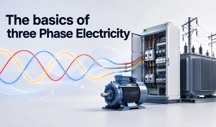
Three-phase power is what runs most commercial buildings in Canada and the United States. If your site has elevators, rooftop HVAC, a commercial kitchen, a machine shop, or a server room with more than a couple of racks, it is almost certainly fed by a three-phase service. This guide explains how it works, what the standard voltages are on both sides of the border, and the practical decisions that come up when a building’s electrical capacity no longer matches its load.
The short answer
Three-phase electricity delivers power through three alternating current waveforms, each shifted 120 degrees apart. Because the three waveforms peak at different moments, the combined power delivered to a balanced load stays constant instead of pulsing. That gives you smoother motor operation, more power through less copper, and higher capacity in the same electrical room footprint than single-phase can provide.
What three-phase electricity actually is
An alternating current supply does not hold a steady voltage. It rises to a positive peak, falls back through zero, drops to a negative peak, and returns. In North America this happens 60 times per second.
A single-phase supply has one of these waveforms. Twice per cycle the voltage passes through zero, and at those instants the supply delivers no power at all. For a light bulb or a laptop charger this does not matter. For a 40 horsepower chiller compressor, it means torque arrives in pulses rather than a steady push.
Three-phase supplies three separate waveforms on three conductors, spaced evenly through the cycle at 120 degrees. When one phase is passing through zero, the other two are carrying current. Add the instantaneous power of all three together across a balanced load and the total is flat. There is no gap.
Single-phase vs three-phase at a glance
| Characteristic | Single-phase | Three-phase |
|---|---|---|
| Live conductors | 1 (plus neutral) | 3 (plus neutral in wye systems) |
| Power delivery | Pulses, drops to zero twice per cycle | Constant under balanced load |
| Typical capacity | Up to roughly 200 A at 240 V | Hundreds to thousands of amps |
| Motor starting | Needs capacitors or a start winding | Self-starting, no extra components |
| Copper for the same power | Baseline | Roughly 25 percent less |
| Typical use | Homes, small retail, light commercial | Offices, industrial, data centres, large retail |
Standard three-phase voltages in Canada and the United States
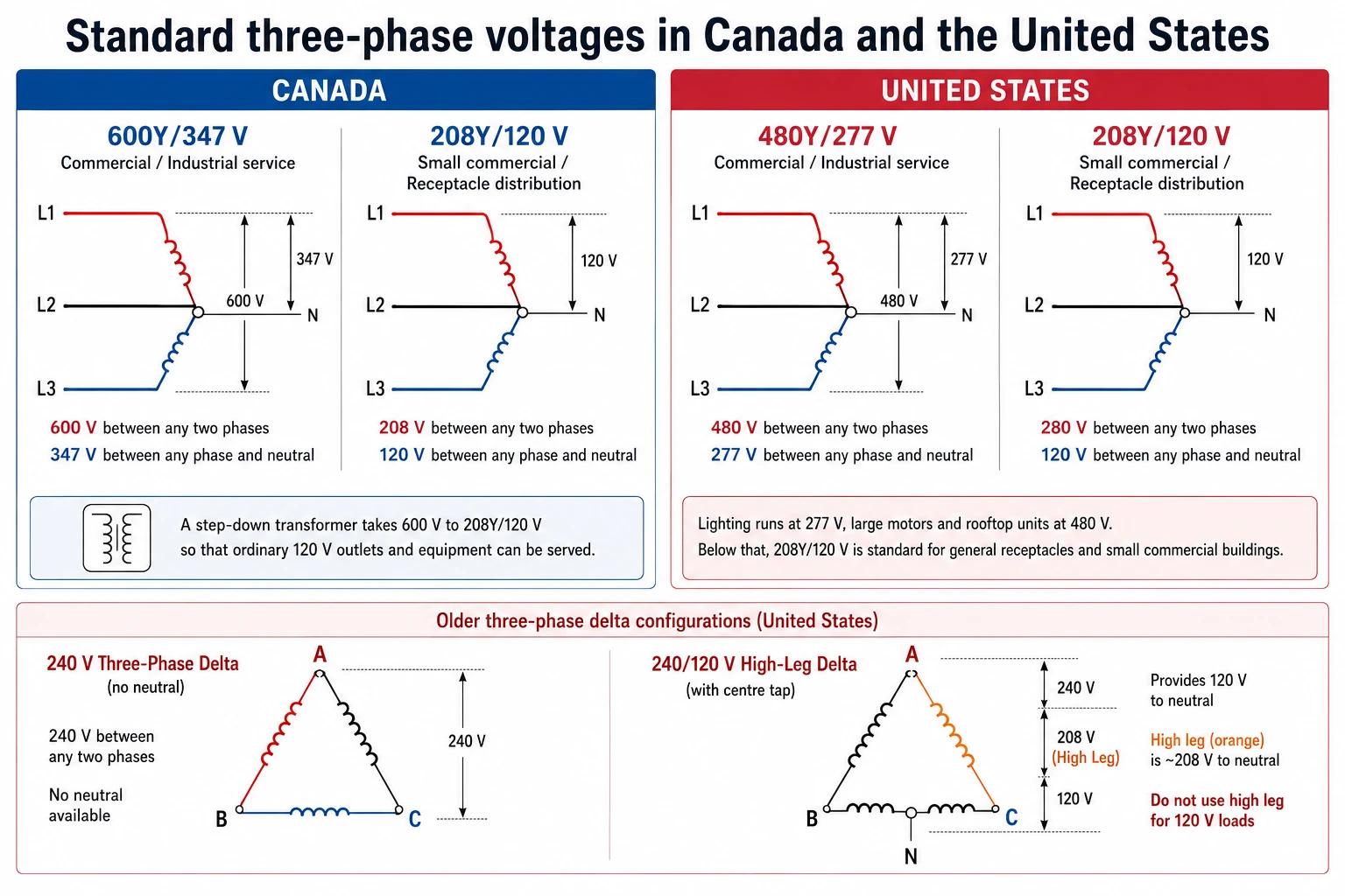
This is where the two countries diverge, and it catches out equipment buyers regularly. A piece of gear specified for a US 480 V system will not simply drop into a Canadian 600 V panel, and vice versa.
Canada
Canadian commercial and industrial buildings commonly run 600Y/347 V. The 600 V figure is the voltage measured between any two phase conductors. The 347 V figure is measured between one phase and neutral, and it is what feeds most commercial lighting circuits in office towers and warehouses.
Smaller commercial buildings, and the receptacle-level distribution inside larger ones, typically run 208Y/120 V. A step-down transformer takes 600 V to 208Y/120 V so that ordinary 120 V outlets and equipment can be served.
United States
The US equivalent of Canadian 600 V service is 480Y/277 V. Lighting runs at 277 V, large motors and rooftop units at 480 V. Below that, 208Y/120 V is the standard for general receptacles and small commercial buildings, exactly as in Canada.
Two delta configurations still appear in older US buildings. A 240 V three-phase delta service has no neutral. A 240/120 V high-leg delta adds a centre tap on one winding to provide 120 V, which leaves one conductor sitting at about 208 V to neutral. That high leg is marked orange and must never be used for 120 V loads.
| System | Country | Line to line | Line to neutral | Common use |
|---|---|---|---|---|
| 600Y/347 V | Canada | 600 V | 347 V | Main service, HVAC, lighting, large motors |
| 480Y/277 V | US | 480 V | 277 V | Main service, HVAC, lighting, large motors |
| 208Y/120 V | Both | 208 V | 120 V | Receptacles, IT equipment, small commercial |
| 240 V delta | Mostly US | 240 V | None | Legacy motor loads |
| 240/120 V high-leg delta | US only | 240 V | 120 V and 208 V (high leg) | Older mixed-load buildings |
Wye and delta: the two ways to connect three phases
Three windings can be joined in two shapes, and the choice affects what voltages you can take off the system.
In a wye connection, one end of each winding ties to a shared neutral point. The other three ends become the phase conductors. This gives you two usable voltages from one system: the higher line-to-line value and the lower line-to-neutral value. The relationship between them is the square root of three, about 1.732. That is why 600 divided by 1.732 gives 347, and 480 divided by 1.732 gives 277.
In a delta connection, the three windings form a closed triangle with no neutral point. Only one voltage is available, measured between any two corners. Delta is common on the primary side of distribution transformers and on legacy motor feeds.
| Wye (Y) | Delta (Δ) | |
|---|---|---|
| Neutral available | Yes | No (unless centre-tapped) |
| Voltages available | Two (line-line and line-neutral) | One |
| Line current | Equals phase current | √3 × phase current |
| Line voltage | √3 × phase voltage | Equals phase voltage |
| Typical role | Building distribution, mixed loads | Transformer primaries, motor loads |
| Ground fault detection | Straightforward via the neutral | Requires added detection |
Distribution transformers are frequently built delta-wye. The delta primary blocks certain harmonic currents from passing upstream, and the wye secondary provides the neutral the building needs.
How three-phase power reaches your building
Generation
Three-phase power comes out of an alternator. A rotating magnetic field, driven by a turbine, spins inside a stator that carries three sets of windings positioned one third of a turn apart. As the field sweeps past each winding it induces a voltage, and because the windings are physically offset, the three voltages are offset in time by 120 degrees. The phase relationship is a product of the machine’s geometry, not electronics.
Transmission
Transformers step the generated voltage up to transmission levels, often 115 kV to 500 kV. Higher voltage means lower current for the same power, and losses in a conductor rise with the square of the current. Moving power at high voltage is what makes long-distance transmission viable.
Distribution and the service entrance
Substations step voltage back down for local distribution, typically to somewhere between 4 kV and 35 kV. A pad-mounted or vault transformer near the building makes the final step to 600Y/347 V or 480Y/277 V. From there the service conductors run to the main switchgear, then out to panels, motor control centres, and step-down transformers feeding 208Y/120 V panels.
Why commercial buildings use three-phase
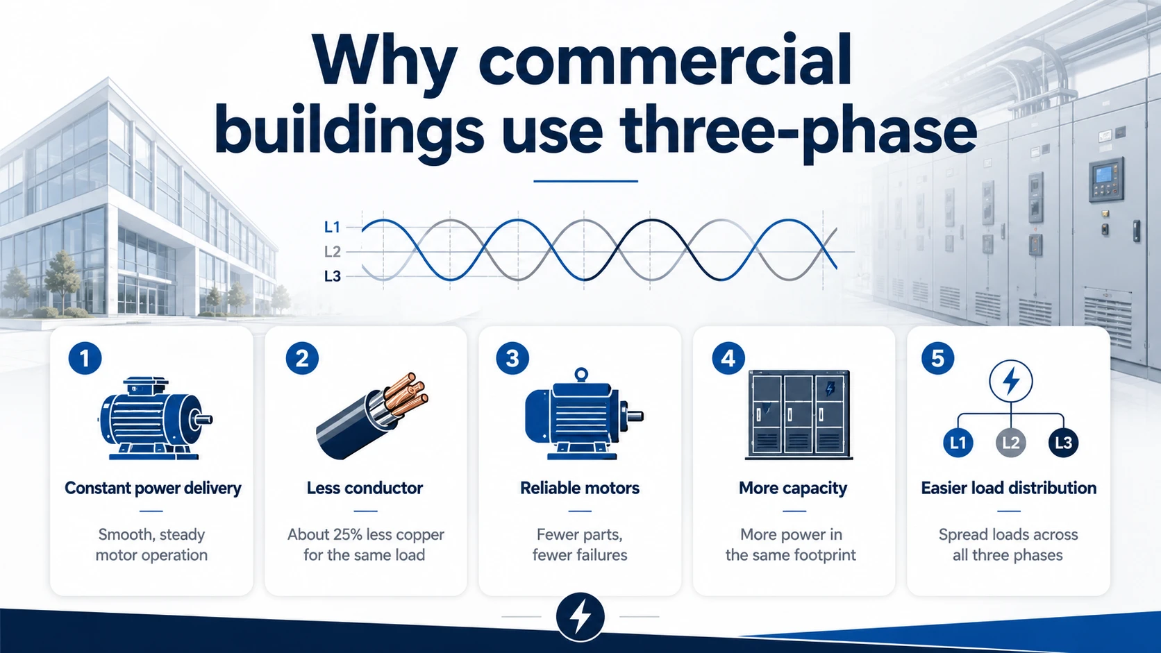
- Constant power delivery. The combined output of three balanced phases does not dip. Motors run with steady torque and less vibration, which extends bearing and coupling life.
- Less conductor for the same load. Delivering a given amount of power over three phases needs roughly 25 percent less copper than doing it single-phase. On a long feeder run that is a meaningful material and labour saving.
- Simpler, more reliable motors. A three-phase induction motor produces a rotating magnetic field on its own. It needs no start capacitor, no centrifugal switch, and no auxiliary winding. Fewer parts means fewer failures.
- More capacity in the same footprint. A 600 V three-phase service can move several times the power of a single-phase service through gear of comparable physical size.
- Easier load distribution. Single-phase loads can be spread across the three phases so no single conductor carries the whole burden.
The three-phase calculations worth knowing
Two formulas cover most day to day questions.
Real power: P (watts) = √3 × line voltage × line current × power factor
Apparent power: S (volt-amperes) = √3 × line voltage × line current
A worked example. A rooftop unit draws 42 A at 600 V with a power factor of 0.88.
- Apparent power: 1.732 × 600 × 42 = 43,646 VA, or about 43.6 kVA
- Real power: 43,646 × 0.88 = 38,409 W, or about 38.4 kW
The same unit on a US 480 V system would draw about 52 A for the same kilowatts. Lower voltage always means higher current for equivalent power, which is why conductor sizing has to be checked whenever equipment is moved between the two systems.
Working backwards is just as useful. To find the current a known kW load will draw: I = P ÷ (√3 × V × PF). A 30 kW load at 208 V with a 0.9 power factor pulls about 92.5 A, which puts it beyond a 100 A feeder once the 80 percent continuous load rule is applied.
Load balancing and why it matters
A balanced three-phase load draws equal current on all three phases. Motors and most large HVAC equipment are inherently balanced because they are built as three-phase devices.
The imbalance comes from single-phase loads. Every 120 V receptacle, every lighting circuit, and every rack of servers is connected to one phase. If an electrician loads phase A heavily and leaves phase C light, several things follow:
- Neutral current rises. In a perfectly balanced wye system the neutral carries almost nothing. Imbalance pushes real current onto it.
- Voltage on the heavily loaded phase sags, while the lightly loaded phase drifts high.
- Three-phase motors on the same system run hotter. A voltage imbalance of a few percent can raise winding temperature substantially and shorten motor life.
- Usable capacity drops. The service is limited by its most heavily loaded phase, so an unbalanced panel effectively wastes the headroom on the other two.
There is a second issue specific to buildings full of electronics. Switch-mode power supplies draw current in short pulses rather than smooth sine waves, which generates third harmonic current. Unlike the fundamental, third harmonics from all three phases add together in the neutral rather than cancelling. In older installations this can push neutral current above phase current, which is why shared neutrals and undersized neutral conductors are a genuine hazard in IT-heavy buildings. Modern supplies with active power factor correction have reduced the problem, but legacy equipment and cheap PSUs still produce it.
Power factor and what it costs you
Power factor is the ratio of real power (kW, the part doing useful work) to apparent power (kVA, the total the utility has to supply). A purely resistive load such as a heater has a power factor of 1. Inductive loads such as motors and transformers pull current slightly out of step with voltage, which drops the power factor below 1.
The practical consequence is that a facility with a 0.75 power factor needs about 33 percent more current than one at 1.0 to accomplish the same work. That current still heats conductors and still occupies transformer capacity. Many utilities respond by billing demand in kVA rather than kW, or by applying a penalty once power factor drops below a threshold, commonly around 0.90.
Correction is usually straightforward. Capacitor banks offset the inductive reactance of motor loads and can be switched in automatically as load varies. On sites with significant harmonic content, detuned or harmonic-filtered capacitor banks are needed to avoid resonance problems. Variable frequency drives on large motors also help, both by improving power factor and by cutting energy use at part load.
Planning an equipment change or a fit-out? Load calculations, panel capacity and phase balancing should be checked before equipment is ordered, not after it arrives. Cablify’s licensed commercial electricians handle panel upgrades, service assessments and lighting control work across the GTA. Call 1-877-450-2134.
Faults and protection in three-phase systems
Three-phase systems fail in ways single-phase systems cannot, and the protection scheme has to account for each.
Common fault types
- Single-phasing. One phase is lost while the other two remain energised. A running three-phase motor will keep turning but draws heavily increased current on the remaining phases and can burn out within minutes. Phase loss relays are the standard protection.
- Phase-to-phase faults. Two conductors make contact, usually through failed insulation. Fault currents are high and clearing has to be fast.
- Ground faults. Current finds a path to earth. In wye systems the neutral connection makes these straightforward to detect. Ground fault protection is required on larger services.
- Reversed phase rotation. If two phases are swapped during a repair, three-phase motors run backwards. On a pump or compressor that can cause damage on the first start.
- Voltage imbalance. Not a fault in itself, but a persistent condition that degrades motors and should be monitored.
Protection devices
Moulded case and power circuit breakers handle overcurrent at the panel and switchgear level. Fuses are still widely used ahead of large motors for their fast clearing under high fault current. Protective relays add selective coordination on larger systems, using overcurrent, differential and distance schemes so that a fault trips the nearest upstream device rather than taking out the whole building.
Arc flash is a serious risk at 600 V and 480 V. Work on energised three-phase gear is governed by CSA Z462 in Canada and NFPA 70E in the United States, both of which require hazard assessment, appropriate PPE, and labelling of equipment with incident energy levels. This is not work for facility staff without the training and rating to do it.
Three-phase power in server rooms and data centres
Anyone building out IT infrastructure runs into three-phase quickly. A rack that once drew 3 kW now commonly draws 10 kW or more, and dense compute racks go far beyond that.
- Three-phase rack PDUs bring 208Y/120 V into the cabinet and split the outlets across all three phases. A three-phase 30 A PDU delivers roughly 8.6 kW where a single-phase 30 A unit at 208 V manages about 5 kW.
- Phase balance inside the rack matters as much as at the panel. Populating outlets without tracking which phase they sit on leads to one phase tripping while the other two sit at half load.
- Dual A and B feeds from separate UPS systems need balance considered on both paths, since either has to carry the full load if the other drops.
- Cooling is three-phase too. CRAC and CRAH units, chillers and condensers are all three-phase motor loads and often represent 30 to 40 percent of the room’s total draw.
- Cable pathways have to keep power and data separated. Power feeders running alongside copper data cable can induce noise. Proper separation and pathway design is part of any competent server room cabling build.
When a room is being expanded, the power and cabling work should be planned together. Retrofitting pathways after the PDUs are mounted costs more and usually produces a worse result. The same applies to cable management in existing rooms where airflow and power density have both crept up over time.
Signs your building needs a three-phase upgrade
- Breakers trip when several large loads run at once, with no identifiable fault.
- Lights dim noticeably when HVAC or a large motor starts.
- Equipment you want to buy is only available in a three-phase version.
- Your utility bill shows a power factor penalty or a kVA demand charge climbing faster than consumption.
- The main panel has no spare breaker positions and no room for a subpanel.
- You are adding EV charging, a server room, or production equipment to a building that was not designed for it.
- Phase currents measured at the main are significantly unequal.
Where a full service upgrade is not practical, a phase converter can supply three-phase equipment from a single-phase service. Rotary converters suit motor loads reasonably well. Static converters are cheaper but derate the motor and are not appropriate for continuous duty. Neither is a substitute for a proper service where the building load justifies one.
Codes, permits and who is allowed to do the work
In Ontario, electrical installations fall under the Ontario Electrical Safety Code. The current version is the 29th edition, published in 2024 and in force since May 1, 2025. It adopts CSA C22.1:24, the Canadian Electrical Code Part I, with Ontario-specific amendments. Work has to be carried out by a Licensed Electrical Contractor, and notification of work must be filed with the Electrical Safety Authority. Other provinces adopt the Canadian Electrical Code with their own amendments and their own permit process.
In the United States, installations follow NFPA 70, the National Electrical Code. The 2026 edition is the current one, though adoption is set state by state and some jurisdictions still enforce an earlier edition. The authority having jurisdiction is the final word on which version applies and what inspection is required.
Service upgrades also involve the local utility. Capacity has to be confirmed, and transformer or service conductor changes are coordinated with them. That step often sets the schedule, so it is worth starting early.
Frequently asked questions
Can I run a three-phase motor on single-phase power?
Only through a phase converter or a variable frequency drive rated for single-phase input. A VFD is usually the better option for a single machine, since it also gives you soft starting and speed control. Expect to derate the drive, often to around half its three-phase rating.
Why is Canadian commercial power 600 V when the US uses 480 V?
It is a historical standards decision rather than a technical one. Canadian utility practice settled on 600 V as the standard low-voltage class while US practice settled on 480 V. Both work equally well. The practical effect is that equipment, transformers and lighting ballasts are country-specific, and cross-border equipment purchases need checking.
What does 208 V come from if the service is 600 V?
A step-down transformer inside the building, typically 600 V delta to 208Y/120 V wye. The 208 V figure is the line-to-line voltage of that secondary, and 120 V is line-to-neutral. Nothing is “converted” in the sense of changing phase count. The transformer just changes voltage.
How do I know if my building already has three-phase service?
Check the main service panel. A three-phase panel has three main conductors feeding the bus and three-pole breakers. The nameplate will state the voltage as 600Y/347, 480Y/277 or 208Y/120 and list the phase count. Do not open the panel to check unless you are qualified to work near energised equipment.
What is an acceptable level of phase imbalance?
Most equipment manufacturers want voltage imbalance held under 2 percent, and many motor warranties reference 1 percent. Current imbalance tolerances are looser but persistent imbalance above roughly 10 percent is worth investigating.
Does three-phase power cost more?
The energy itself is not billed differently, but commercial three-phase accounts usually carry a demand charge based on peak draw, and sometimes a kVA charge that penalises poor power factor. Against that, three-phase equipment runs more efficiently, so total operating cost is often lower for a building with substantial motor load.
Why does the neutral sometimes carry more current than the phases?
Third harmonic currents produced by non-linear single-phase loads add together in the shared neutral instead of cancelling. In buildings with heavy electronics load and older wiring this can push neutral current above phase current, which is why oversized neutrals and dedicated neutrals per circuit are specified in IT environments.
What is the difference between kW and kVA?
kW is the real power doing useful work. kVA is the total power the supply must provide, including the reactive component that circulates without doing work. Power factor is the ratio between them. Generators, UPS units and transformers are rated in kVA because that is what limits their capacity.
Getting the electrical side right
Three-phase power is not complicated in principle. Three waveforms, evenly spaced, adding up to something steady. The complications come from the details: which voltage standard applies, how the loads are distributed, whether the neutral is sized for the harmonics your equipment produces, and whether the service has capacity for what you are planning to add.
Cablify has worked on commercial electrical and cabling projects across the Greater Toronto Area for over 18 years, covering Toronto, Mississauga, Brampton, Vaughan, Hamilton, Oakville and beyond. If you are planning a panel upgrade, a fit-out, or a structured cabling and power build for a new space, we can assess what you have and what you need.
Talk to a licensed commercial electrician
Service assessments, panel upgrades, three-phase equipment connections and server room power and cabling. Toll free 1-877-450-2134 or local 1-647-846-1925. Request a quote.