
Single Mode vs Multimode Fiber:
The Complete Guide to Choosing Right
Single mode or multimode? It’s the first decision in every fiber installation — and the wrong answer means re-pulling cable that cost thousands to install. This guide covers everything you need to choose correctly, every time.
Fiber optic cable carries light instead of electricity — which is why it achieves speeds and distances that copper cable simply cannot match. But not all fiber is the same. The choice between single mode fiber (SMF) and multimode fiber (MMF) determines your distance capability, bandwidth ceiling, cost, transceiver type, and whether your infrastructure will still make sense in five years. Getting it wrong is expensive. Getting it right is straightforward once you understand what’s actually happening inside the cable.
This guide covers every dimension of the SMF vs MMF decision: the physics of how light propagates differently in each type, the complete distance and bandwidth specifications, colour coding and how to tell them apart, patch cord compatibility, real-world pricing, the disadvantages of each type nobody talks about, and a definitive decision framework for 2026. We also answer the specific questions that bring most people to this page — including whether 50 micron fiber is single mode, what the single mode wavelengths actually are, and whether multimode is always better for short runs.
How Fiber Optic Cable Actually Works
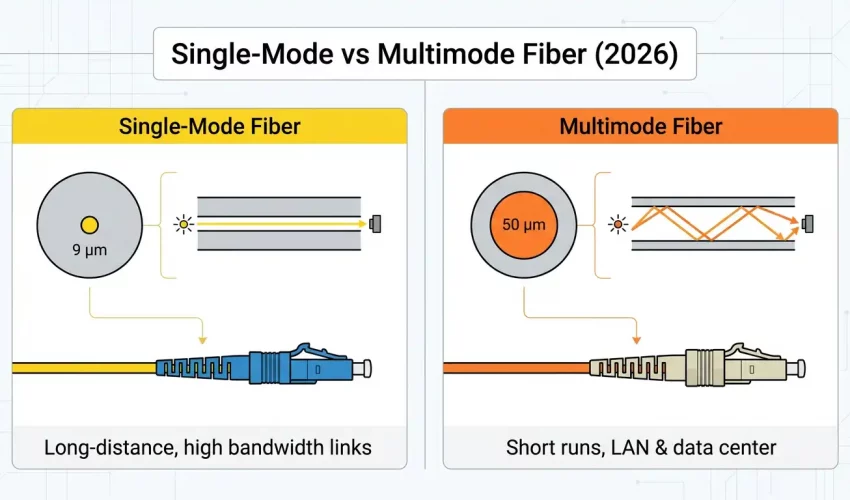
To understand why single mode and multimode fiber perform so differently, you need a basic picture of what happens inside the cable. Both types transmit data as pulses of light. Both consist of three concentric layers: a core (where light travels), cladding (a glass layer with a lower refractive index that reflects light back into the core), and a protective coating.
The core and cladding work together through a phenomenon called total internal reflection — light hits the cladding at an angle and bounces back into the core rather than escaping. This is what keeps the light signal contained and travelling along the fiber’s length.
The critical difference is what happens to light inside the core. In a 9µm single mode core, the core is so narrow that only a single wavelength of light can propagate straight through — there’s essentially only one path. In a 50µm or 62.5µm multimode core, the core is wide enough for many light rays to travel simultaneously at slightly different angles, each bouncing off the cladding at a different trajectory. These are the “modes.”
The problem with multiple modes is modal dispersion: each mode travels a slightly different path length and therefore arrives at the far end at a slightly different time. A sharp pulse of light sent in becomes a spread-out smear at the other end. The more modes, the worse the dispersion, and the shorter the maximum distance before the signal becomes unreadable.
Core Size, Cladding, and Physical Structure
Both fiber types share the same outer cladding diameter of 125 microns — this is an industry standard that ensures compatibility with connectors, splices, and mechanical hardware. The dramatic difference is in the core.
| Parameter | Single Mode (SMF) | Multimode — OM1/OM2 | Multimode — OM3/OM4/OM5 |
|---|---|---|---|
| Core diameter | 8–9 µm (typically 9µm) | 62.5 µm | 50 µm |
| Cladding diameter | 125 µm | 125 µm | 125 µm |
| Coating diameter | 245 µm (standard) | 245 µm | 245 µm |
| Light source | Laser diode only | LED or VCSEL | VCSEL (laser) |
| Wavelength | 1310 nm and 1550 nm | 850 nm and 1300 nm | 850 nm (primary) |
| Numerical Aperture | 0.10–0.14 | 0.275 | 0.200 |
No. 50 micron fiber is multimode — specifically the OM3, OM4, and OM5 grades. Single mode fiber has a core diameter of 8–9 microns. The core must be smaller than approximately 10 microns at the operating wavelength to support only a single propagation mode. 50 micron fiber is about 5–6 times larger than single mode core, which is why it supports hundreds of modes simultaneously.
Multimode Fiber Grades: OM1 Through OM5 Explained
Not all multimode fiber is equal. The ISO/IEC 11801 standard defines five grades of multimode fiber — OM1 through OM5 — with progressively better bandwidth and distance performance. Understanding these grades is essential for specifying the right cable for data center and campus deployments in 2026.
| Grade | Core | Jacket Colour | Bandwidth (850nm) | Max Distance @ 10G | Max Distance @ 100G | Status |
|---|---|---|---|---|---|---|
| OM1 | 62.5µm | 🟠 Orange | 200 MHz·km | 33 m | N/A | Legacy only |
| OM2 | 50µm | 🟠 Orange | 500 MHz·km | 82 m | N/A | Legacy only |
| OM3 | 50µm | 🩵 Aqua | 2,000 MHz·km | 300 m | 70 m | Acceptable |
| OM4 | 50µm | 🟣 Violet/Magenta | 4,700 MHz·km | 400 m | 100 m | Recommended |
| OM5 | 50µm | 🟢 Lime green | 28,000 MHz·km | 400 m | 150 m | Best MMF 2026 |
OM5 fiber — often called “wideband multimode fiber” — is designed to support short wavelength division multiplexing (SWDM), transmitting multiple wavelengths simultaneously over a single fiber strand. This allows higher aggregate data rates without requiring additional fibers, making it valuable in high-density data center environments where fiber count is at a premium.
Single Mode Fiber Grades: OS1 and OS2
Single mode fiber has two primary grades defined by ISO/IEC 11801: OS1 and OS2. The difference is not in the fiber glass itself — both have a 9µm core — but in the cable construction and maximum attenuation.
| Grade | Jacket Colour | Max Attenuation | Construction | Best For |
|---|---|---|---|---|
| OS1 | 🟡 Yellow | 1.0 dB/km | Tight buffered (indoor) | Indoor runs up to ~10 km — office buildings, campuses |
| OS2 | 🟡 Yellow | 0.4 dB/km | Loose tube (outdoor/long-haul) | Long-haul, outdoor, direct burial — up to 200+ km |
Both OS1 and OS2 use the same yellow jacket — which can cause confusion. The distinction matters significantly for long runs: OS2’s lower attenuation (0.4 dB/km vs 1.0 dB/km) roughly doubles the practical distance before signal amplification is needed. For all outdoor and inter-building single mode runs, specify OS2.
Single Mode Fiber Wavelength — What 1310nm and 1550nm Mean
Single mode fiber operates at two primary wavelengths: 1310 nanometres and 1550 nanometres. These are not interchangeable choices — they have distinct characteristics that determine which is appropriate for a given application.
| Wavelength | Type | Key Property | Primary Use |
|---|---|---|---|
| 850 nm | Multimode | Short wavelength, lower cost VCSELs | OM3/OM4/OM5 data center and LAN runs up to 400m |
| 1300 nm | Multimode (also SMF) | Lower modal dispersion than 850nm in MMF | Longer multimode runs; early SMF applications |
| 1310 nm | Single mode | Zero dispersion point in standard SMF | Metro networks, campus backbones, medium-haul (up to 40km) |
| 1550 nm | Single mode | Lowest attenuation (0.2 dB/km) in silica fiber | Long-haul, DWDM, submarine, EDFA amplification |
| 1490 / 1577 nm | Single mode | CWDM and DWDM channel wavelengths | Wavelength-division multiplexed networks (40+ channels) |
The 1550nm window is particularly important for long-haul applications because it coincides with the gain bandwidth of Erbium-Doped Fiber Amplifiers (EDFAs) — the technology that allows optical signals to be amplified directly without converting to electrical signals first. This is what makes 1550nm the backbone of intercontinental and submarine fiber networks.
Single Mode vs Multimode Fiber Distance — Complete Chart
Distance is where the SMF vs MMF decision is most often made. Here is a complete reference chart covering all current standards:
| Data Rate | Standard | OM3 Distance | OM4 Distance | OM5 Distance | OS2 (SMF) Distance |
|---|---|---|---|---|---|
| 1 Gbps | 1000BASE-SX/LX | 550 m | 550 m | 550 m | 5 km (LX) / 70 km (EX) |
| 10 Gbps | 10GBASE-SR/LR | 300 m | 400 m | 400 m | 10 km (LR) / 40 km (ER) / 80 km (ZR) |
| 25 Gbps | 25GBASE-SR/LR | 70 m | 100 m | 100 m | 10 km (LR) |
| 40 Gbps | 40GBASE-SR4/LR4 | 100 m | 150 m | 240 m | 10 km (LR4) / 40 km (ER4) |
| 100 Gbps | 100GBASE-SR4/LR4 | 70 m | 100 m | 150 m | 10 km (LR4) / 40 km (ER4) |
| 400 Gbps | 400GBASE-SR8/LR8 | 50 m | 100 m | 150 m | 10 km (LR8) / 2 km (DR4) |
For most Toronto and GTA office buildings, multimode OM4 is sufficient for all intra-building fiber runs — the maximum distance between an MDF and any IDF in a single building rarely exceeds 100 metres. Single mode becomes the correct choice when connecting buildings across a campus (typically 100m–2km), running between facilities across a city (2km–40km), or for any run where future distance expansion is anticipated. If your fiber will ever leave the building, specify single mode.
Single Mode vs Multimode Fiber Bandwidth — What the Numbers Actually Mean
Bandwidth in fiber optic cable is expressed in MHz·km — megahertz kilometres. This is a composite unit that tells you the bandwidth available over a given distance. A cable rated at 4,700 MHz·km can carry 4,700 MHz of bandwidth over 1 kilometre, or 470 MHz over 10 kilometres. As distance increases, available bandwidth decreases proportionally.
Single mode fiber has effectively unlimited bandwidth in practical terms — there is no modal dispersion limiting it, only chromatic dispersion and the capacity of the transceiver at each end. Current deployed single mode systems routinely operate at 400 Gbps per wavelength, and research demonstrations have exceeded 10 Tbps per fiber using DWDM with hundreds of wavelength channels simultaneously.
Multimode fiber bandwidth is fundamentally limited by modal dispersion. No matter how good the transceiver or the switch, you cannot exceed the bandwidth-distance product of the fiber itself. This is why OM4 at 100 Gbps is limited to 100 metres — beyond that, modal dispersion has spread the pulses too much to distinguish individual bits reliably.
Fiber Optic Colour Coding — How to Tell Single Mode from Multimode at a Glance
The TIA-598 standard defines colour coding for fiber optic cables and connectors. Knowing these colours prevents the most common and most expensive fiber installation mistake: connecting a single mode transceiver to multimode cable (or vice versa), which produces near-zero signal and takes hours to diagnose.
| Jacket Colour | Fiber Type | Grade | How to Confirm |
|---|---|---|---|
| 🟡 Yellow | Single Mode | OS1 or OS2 | Laser-only transceivers; connector ferrule often blue (PC) or green (APC) |
| 🟠 Orange | Multimode | OM1 (62.5µm) or OM2 (50µm) | Legacy; check printed core size on jacket |
| 🩵 Aqua | Multimode | OM3 (50µm) | Common in data centers; aqua connectors often included |
| 🟣 Violet / Magenta | Multimode | OM4 (50µm) | Most common modern multimode; violet housing on LC connectors |
| 🟢 Lime Green | Multimode | OM5 (50µm) | Newest standard; lime green is unmistakable |
Plugging a single mode transceiver (yellow SFP) into a multimode fiber patch cord — or vice versa — produces near-zero optical signal. The transceiver won’t error out with a clear message. The link simply won’t come up, or will show signal but drop packets constantly. We’ve seen GTA businesses spend entire days troubleshooting a “switch issue” or “bad SFP” when the actual cause was a yellow cable plugged into an aqua port because both LC connectors look identical. Colour-code everything and label it.
Single Mode vs Multimode Patch Cords — Connectors, Polish, and Compatibility
Patch cords (also called jumpers) are the short fiber cables used to connect equipment to patch panels, or switches to transceivers. Understanding patch cord specifications prevents the compatibility issues that cause most day-to-day fiber problems.
Connector Types
Both SMF and MMF patch cords use the same physical connector types — the connectors themselves are not fiber-type specific. The most common:
- LC (Lucent Connector) — Small form factor, 1.25mm ferrule. The dominant standard for data center and enterprise equipment. Most SFP, SFP+, and QSFP transceivers use LC duplex.
- SC (Subscriber Connector) — Larger 2.5mm ferrule, push-pull coupling. Common in older equipment and telco applications. Still widely used in patch panels.
- MPO/MTP — Multi-fiber push-on. 8, 12, or 24 fibers in a single connector. Used for 40G, 100G, and 400G parallel optics applications with trunk cables.
- ST (Straight Tip) — Bayonet-style coupling, older standard. Rarely specified in new installations but still found in legacy infrastructure.
End Polish Types — This Is Where It Gets Critical for Single Mode
| Polish Type | Connector Colour | Return Loss | Compatible With | Use |
|---|---|---|---|---|
| UPC (Ultra Physical Contact) | Blue ferrule | ≥ 50 dB | SMF and MMF | Standard SMF patch cords, data networks |
| APC (Angled Physical Contact) | Green ferrule | ≥ 60 dB | SMF only | FTTH, CATV, high-sensitivity SMF systems |
| PC (Physical Contact) | Black ferrule | ≥ 40 dB | SMF and MMF | Legacy only — not recommended for new installs |
UPC and APC connectors are physically compatible — they will mate. But connecting a UPC to an APC port introduces approximately 0.5–3 dB of return loss, which can cause signal issues, reflections that damage laser sources, and intermittent link failures. The green vs blue colour coding exists specifically to prevent this. In any single mode installation, be consistent — use all UPC or all APC throughout a link. Never mix.
Single Mode vs Multimode Fiber Price — The Complete Cost Picture
The cost comparison between SMF and MMF is more nuanced than “single mode costs more.” The cable itself is one component — the transceivers at each end are often the larger cost driver, and the economics flip at certain distances.
| Cost Component | Single Mode (OS2) | Multimode (OM4) | Verdict |
|---|---|---|---|
| Cable per metre | $0.80 – $1.50/m | $1.00 – $2.50/m | SMF cheaper |
| Patch cord (LC duplex, 3m) | $8 – $25 (UPC) | $6 – $18 | Similar |
| SFP+ transceiver (10G) | $80 – $300 (LR) | $15 – $60 (SR) | MMF cheaper |
| QSFP28 transceiver (100G) | $200 – $600 (LR4) | $40 – $120 (SR4) | MMF cheaper |
| Fusion splicing | Slightly harder, similar cost | Standard | Similar |
| Total system cost (short run, <100m) | Higher (transceiver cost) | Lower | MMF wins short |
| Total system cost (>500m) | Lower (cable cost advantage) | Higher (or impossible) | SMF wins long |
The economic crossover point is approximately 300–500 metres for most 10G and 100G applications. Below this distance, multimode’s cheaper transceivers dominate the system cost. Beyond this distance, single mode’s lower cable cost and the availability of longer-reach optics make it the more economical choice — and beyond 500 metres, multimode simply isn’t an option at high data rates regardless of cost.
Single Mode vs Multimode — Pros and Cons
Advantages of Single Mode Fiber
- Virtually unlimited distance: 10+ km standard; 80–120 km with extended-reach optics; 1,000+ km with optical amplification
- Unlimited bandwidth ceiling: No modal dispersion — bandwidth scales with transceiver technology, not fiber limitation
- Lower attenuation: 0.2–0.4 dB/km vs 2.5–3.5 dB/km for multimode — signal travels further with less loss
- Future-proof: Deploying SMF today means the fiber is never the limiting factor as speeds increase from 10G to 100G to 400G
- DWDM capable: Wavelength-division multiplexing allows 40, 80, or 160+ channels on a single fiber strand — massive capacity from existing infrastructure
- Lower cable cost: Per-metre cable cost is typically lower than OM4/OM5 multimode
Disadvantages of Single Mode Fiber
- Higher transceiver cost: Single mode SFPs and QSFPs cost 3–10× more than equivalent multimode transceivers at short distances — the biggest disadvantage for intra-building runs
- Laser safety: Requires eye-safe laser sources. The 1310nm and 1550nm wavelengths are invisible and cannot be seen with the naked eye — make this a safety consideration during installation
- Tighter alignment tolerances: The 9µm core demands more precise connector alignment and cleaner terminations than the larger multimode core. Dirty or poorly terminated connectors have a larger proportional impact
- APC vs UPC confusion: Managing two polish types that are physically compatible but optically incompatible adds a layer of complexity to installations
Advantages of Multimode Fiber
- Lower transceiver cost: Short-range multimode SFP+ at 10G cost $15–60 vs $80–300 for single mode equivalents — significant saving in data center deployments with many links
- LED-compatible: Older OM1/OM2 fiber works with LED light sources, which are cheap and robust. OM3/OM4/OM5 uses VCSELs — still significantly cheaper than SMF lasers
- Easier to work with: The larger 50µm core is more tolerant of minor misalignment at connectors and splices. Cleaning and inspection is easier
- Sufficient for most intra-building runs: For office floor-to-floor connections within a single building, OM4 at 400m covers virtually any GTA commercial building
- Visual fault detection: A visible red laser (VFL) can be used to identify breaks and verify connectivity in multimode fiber — practical for on-site troubleshooting
Disadvantages of Multimode Fiber
- Hard distance ceiling: 400m for OM4 at 10G, 100m at 100G. If the run ever needs to go further, the fiber must be replaced
- Modal dispersion limits bandwidth: No matter the transceiver, bandwidth-distance product is a fundamental physical limit. You cannot upgrade your way past it without replacing cable
- Grade compatibility complexity: Mixing OM1, OM2, OM3, OM4 in a link degrades performance to the worst segment — a single OM1 patch cord can eliminate the benefit of an entire OM4 installation
- Not suitable for long-haul: Cannot be used for inter-building runs beyond 500m at 10G, or beyond 100m at 100G — limits future flexibility
- Higher cable cost per metre: OM4 and OM5 cable costs more per metre than equivalent OS2 single mode cable
Which Should You Choose? The 2026 Decision Framework
or between
buildings?
OS2 Always
intra-building
data center?
OM4 or OM5
If neither extreme applies clearly, use these rules:
- Choose Single Mode OS2 if: any run exceeds 300m, the cable will leave the building at any point now or in the future, your application requires DWDM or wavelength multiplexing, you’re connecting buildings on a campus, or you want to permanently future-proof the infrastructure regardless of cost
- Choose Multimode OM4 if: all runs are within a single building under 300m, you’re deploying many switch-to-switch links in a data center where transceiver cost is the dominant budget item, and you are confident the runs will never need to extend further
- Choose Multimode OM5 if: you need multimode but want headroom for future 100G+ speeds, or you’re building a data center that will use SWDM (short wavelength division multiplexing) to increase capacity over existing fiber counts
- Avoid OM1 and OM2 in any new installation — these grades cannot support 10GbE at useful distances and are only relevant for maintaining or extending legacy infrastructure
“If the fiber might ever leave the building — even to reach a rooftop antenna, a parking garage camera, or a satellite office across the street — install single mode. The transceiver cost premium today is far less than the cost of re-pulling fiber through a finished building tomorrow.”
— Cablify fiber installation team, GTA commercial projects
Common Questions — Answered
50 micron fiber is multimode — specifically the OM2, OM3, OM4, and OM5 grades. Single mode fiber has a core of 8–9 microns. A 50µm core is far too large to support single mode propagation at any practical wavelength.
The fundamental difference is core size and how light propagates. SMF has a ~9µm core that supports only one light mode (path), eliminating modal dispersion and enabling virtually unlimited distance and bandwidth. MMF has a 50 or 62.5µm core that supports hundreds of simultaneous light modes, which is cheaper to work with over short distances but causes modal dispersion that limits distance and bandwidth.
Not always — it depends on port count and budget. For a small number of links under 100m, multimode OM4 is typically more cost-effective because multimode transceivers are significantly cheaper than single mode equivalents. However, if you’re installing backbone fiber that might ever need to extend between buildings, or you want permanent future-proofing, single mode OS2 is the better choice even for short runs — the cable cost is lower and the future flexibility is worth the transceiver premium.
No — not effectively. The connector is physically compatible (LC to LC, for example) but the mismatch between the 9µm SMF core and the 50µm MMF core causes massive coupling loss at the junction — typically 15–20 dB, which is enough to completely kill the link. Always match patch cord fiber type to the installed cable fiber type.
Single mode fiber operates at two primary windows: 1310nm (the zero-dispersion point in standard silica SMF, used for medium-distance applications up to ~40km) and 1550nm (the lowest attenuation window in silica fiber at 0.2 dB/km, used for long-haul, DWDM, and submarine applications). Both wavelengths are in the infrared spectrum and are invisible to the naked eye — laser safety precautions always apply.
Single mode fiber jacket is always yellow, per TIA-598. The connector ferrule is typically blue (UPC polish) or green (APC polish). Multimode fiber uses orange (OM1/OM2), aqua (OM3), violet or magenta (OM4), or lime green (OM5). Yellow jacket always means single mode — this is the fastest way to identify fiber type in the field.
Need Fiber Optic Installation in Toronto or the GTA?
Cablify installs single mode and multimode fiber optic cabling for offices, data centers, and campus networks across Toronto, Mississauga, Brampton, Oakville, and the GTA. Free site assessment, OTDR testing on every run.
Explore Fiber Cabling Services →
📞 647-846-1925 · info@cablify.ca · Mon–Sat 8am–8pm