

Improper cable installation silently destroys network performance, causing slow speeds, random drops, packet loss and painful troubleshooting—even when switches, routers and access points are top‑tier.
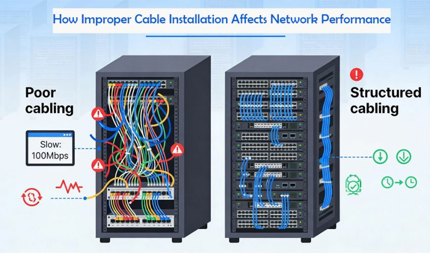
A structured cabling system is the physical foundation of a LAN: copper and fiber links, patch panels, jacks, racks and pathways that connect switches, servers, Wi‑Fi APs, IP phones, CCTV and building systems. Even minor cabling mistakes—wrong category, excessive length, tight bends, sloppy terminations or mixed power/data routing—directly affect throughput, latency and reliability.
1. Why network cabling quality matters more than you think
Even in 10G‑capable networks, performance is often limited by Layer 1: the physical medium.
- Studies and vendor reports note that a large share of “mysterious” slowdowns are traced to substandard or misapplied cabling, not routers or ISPs.
- Poorly organized, unlabeled cabling can consume up to half of troubleshooting time in some data centers, stretching outages and hurting productivity.
Proper structured cabling is designed, installed and tested to standards (TIA‑568, ISO/IEC) so that every permanent link meets performance specs for its category and application.
2. Common improper cabling mistakes and their technical impact
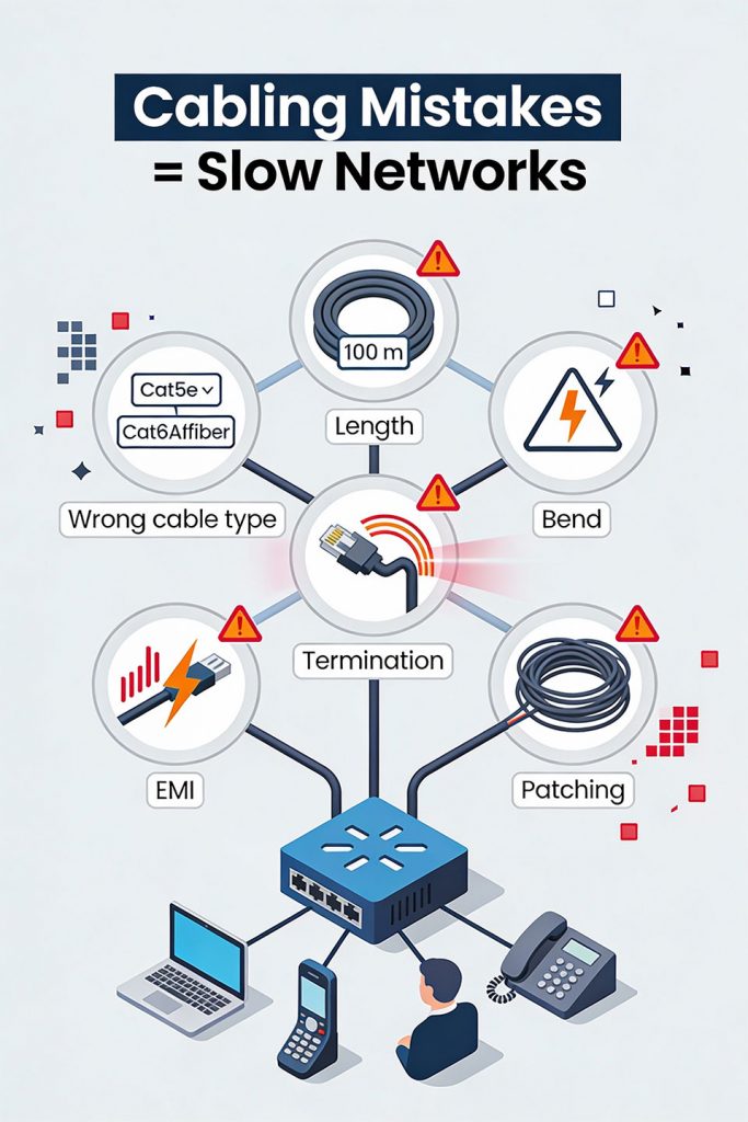
2.1 Wrong cable type or category
Using the wrong medium for distance, speed or environment is one of the fastest ways to bottleneck a network.
Typical mis‑matches:
- Deploying Cat5e for 10G uplinks or dense Wi‑Fi 6/6E APs that really need Cat6A or better.
- Using copper instead of fiber for uplinks over 100 m, causing attenuation and unstable links.
- Running CM/CMR jacket in plenum spaces where CMP is required, creating code and safety issues (not performance, but critical).
Technical impact:
- Bandwidth ceiling: lower categories simply cannot cleanly support higher signalling rates, especially at full 100 m channel length.
- Higher error rate: marginal cabling runs closer to its limit; as SNR drops, bit errors rise, triggering retransmissions and auto‑negotiated speed drops.
Result: even if switches are rated for 1G or 10G, real‑world throughput may behave like Fast Ethernet or worse on poorly chosen cabling.
2.2 Exceeding maximum cable length
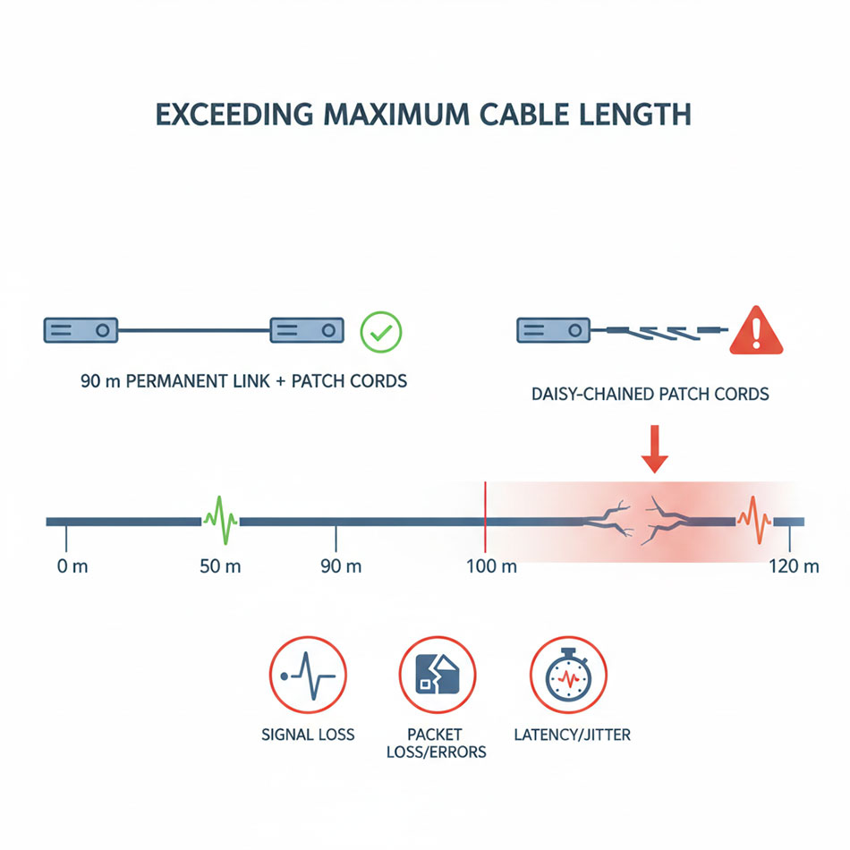
For twisted‑pair Ethernet, the standard channel length is 100 m (90 m permanent link + 10 m patch cords) for Cat5e/Cat6 at 1 Gbps.
Improper installation issues:
- Horizontal runs exceeding 90 m, plus long patch leads, can push the channel beyond 100 m.
- Daisy‑chaining switches with long cords instead of building proper home‑run links.
Technical impact:
- Attenuation (signal loss): as length increases, the electrical signal weakens, reducing SNR.
- Increased bit errors and packet loss: receivers struggle to distinguish bits reliably and start requesting retransmissions or dropping to lower speeds.
- Latency spikes: retransmissions and error handling add delay and jitter, hitting VoIP and video hardest.
Result: networks may pass basic “link up” tests, but deliver inconsistent throughput, especially under load or when temperature/humidity conditions worsen attenuation.
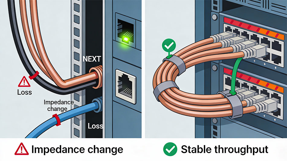
2.3 Ignoring bend radius and cable tension
Excessive bending and pulling are classic structured cabling sins.
Typical installation mistakes:
- Tight 90° bends around tray edges, rack rails, door frames.
- Cables sharply kinked or crushed behind patch panels.
- Over‑tension during pulls through conduits or long pathways.
Technical impact (copper):
- Impedance changes: severe bends change the geometry of the twisted pairs, causing impedance mismatches and reflections.
- Near‑End Crosstalk (NEXT): conductors are forced closer, increasing electromagnetic coupling between pairs, raising NEXT and FEXT.
- Attenuation: signal loss increases at the bend, especially at higher frequencies.
Technical impact (fiber):
- Macrobending losses: tight bends cause light to escape the core, increasing optical attenuation.
- Intermittent loss: slight movement (door closing, tray vibration) can cause transient errors.
Result: link lights may stay green, but throughput suffers, error counters climb, and users see random drops, slow file transfers and poor video quality.
2.4 Poor terminations and unmanaged crosstalk
Bad terminations are one of the top causes of new‑build failures during certification.
Common termination errors:
- Pairs untwisted too far back (beyond 13 mm / 0.5″).
- Mis‑punching conductors on IDC blocks, half‑punches or split pairs.
- Using cheap, non‑compliant connectors or mixing 568A and 568B ends.
- Excessive exposed conductor outside the jack or plug housing.
Technical impact:
- Crosstalk (NEXT/FEXT): untwisted pairs lose their ability to cancel interference, increasing NEXT.
- Return loss: impedance discontinuities at the termination cause reflections, degrading the signal especially in high‑frequency channels.
- Higher BER and packet loss: noisy links trigger retransmissions, degrade throughput and can cause TCP timeouts.
Result: the link might “work” at low load but collapse under traffic, or fail to pass certification at the designed category and speed.
2.5 Poor separation from power and EMI sources
Layer‑1 is very sensitive to electromagnetic interference (EMI).
Improper practices:
- Data cables bundled tightly with power conductors in the same tray.
- Running UTP parallel to fluorescent ballasts, motors, VFDs, elevator gear or HVAC equipment.
- Routing cables over high‑powered UPSs, transformers or large power supplies.
Technical impact:
- Induced noise: power cables create alternating electromagnetic fields; parallel unshielded runs pick up this noise.
- Error bursts: EMI spikes can corrupt bursts of frames, leading to packet loss and visible application hiccups.
Result: intermittent, location‑specific issues (e.g., a row of cubicles near a riser or mechanical room) that are difficult to diagnose until you map cabling to EMI sources.
2.6 Chaotic patching and lack of labeling
Even if individual links are electrically sound, messy patching degrades maintainability and uptime.
Improper practices:
- No labeling on patch panels, jacks or trunks.
- “Spaghetti” patch cords blocking airflow and hiding ports.
- Daisy‑chained switches under desks instead of centralized structured cabling.
Operational impact:
- Longer troubleshooting: technicians spend excessive time tracing cables and guessing endpoints; outages last longer.
- Human error: wrong ports get unplugged, patched or moved during changes, causing unexpected downtime.
- Cooling problems: dense unmanaged bundles impede airflow, causing switches and servers to run hotter, throttle or fail prematurely.
Result: every small incident turns into a multi‑hour disruption because cabling is not logically or physically organized.
3. Symptoms of bad cabling at the network level
Even without visual access to cabling, network metrics reveal physical issues.
Watch for:
- Frequent packet loss: especially on specific ports or VLANs; users complain of dropped calls, frozen video, timeouts.
- CRC and FCS errors: rising CRC/FCS counts indicate corrupted frames at Layer 2.
- Late collisions / alignment errors: on half‑duplex or marginal links, suggesting cable impairments.
- Auto‑negotiation flapping: links repeatedly renegotiate speed/duplex, often dropping from 1G to 100M.
- Port‑specific latency/jitter: trunks or access ports serving problematic areas show higher latency in monitoring tools.
A pattern where specific outlets or zones consistently misbehave is a red flag for localized cabling defects.
4. Business impact: downtime, cost and security
Improper data cabling doesn’t just slow packets; it hurts the business.
- Increased downtime: tangled, unlabeled or defective cabling extends time‑to‑repair; data center surveys indicate that poor cable organization accounts for a large share of troubleshooting time.
- Lost productivity and revenue: frequent Wi‑Fi drops, slow file access and unstable VoIP directly translate into lost hours and unhappy clients.
- Higher maintenance cost: repeated site visits, ad‑hoc repairs and re‑pulls cost more than doing structured cabling properly once.
- Security and compliance risks: physical chaos encourages “temporary” unmonitored connections, forgotten devices and bypassed cable routes that undermine segmentation and change control.
A well‑designed structured cabling system reduces these risks by providing predictable performance, clear labeling and standards‑based installation.
5. Structured cabling best practices to prevent performance problems
5.1 Plan your structured cabling design
Good performance starts at the design phase.
- Perform a site survey: identify telecom rooms, pathways, EMI sources, fire barriers and plenum spaces.
- Design to standards: TIA‑568, TIA‑569 (pathways), TIA‑606 (administration) and ISO equivalents—this ensures interoperability and predictable performance.
- Reserve capacity: size racks, cable trays and conduits for future growth, not just day‑one loads.
5.2 Select the right cabling and components
Choosing proper cable and hardware is essential.
- Match category and medium to application:
- Cat6 or Cat6A for new 1G/10G copper runs in office networks.
- Fiber for long runs (>100 m) or high‑speed distribution/backbone links.
- Follow fire code and environment: plenum‑rated where required, riser or general‑purpose where appropriate.
- Use reputable brands and matching connectors (jacks, patch panels, plugs) to maintain category integrity.
5.3 Respect length and bend radius
Implement physical rules rigorously.
- Keep permanent copper links at or under 90 m, with total channels ≤ 100 m including patch cords.
- For bend radius:
- Avoid sharp bends behind racks; use sweeping curves and radius‑friendly hardware (J‑hooks, wide‑radius corners).
These practices maintain impedance, reduce attenuation and prevent crosstalk.
5.4 Terminate and test every link
High‑quality terminations and certification are non‑negotiable in structured cabling.
- Follow a single pinout (TIA‑568B or A) consistently across the site.
- Minimize untwisting; keep pair twists as close to the contact point as possible.
- Use professional tools: quality punch‑down tools, crimpers and cable strippers reduce human error.
- Certify each link with a cable analyzer at the intended category and test parameters (NEXT, FEXT, return loss, attenuation, length, propagation delay).
Certification reports create a baseline and make it easy to prove the cabling plant is not the problem when issues arise later.
5.5 Separate data from power and EMI sources
Route cables to minimize interference.
- Maintain separation distances between UTP and power lines; use separate conduits or pathways where possible.
- Cross unavoidable power lines at 90°, not in parallel.
- Avoid running data cables near high‑EMI equipment (motors, transformers, elevator machinery, large UPS units).
- Consider shielded or F/UTP cabling in particularly noisy environments, but only with proper grounding.
5.6 Labeling, documentation and cable management
A structured cabling system is as much about admin and management as copper and fiber.
- Label both ends of every permanent link and patch panel port according to a documented scheme (e.g., TIA‑606).
- Use Velcro straps instead of tight zip‑ties to bundle cables without crushing them.
- Maintain updated floor plans, rack elevations and patching schedules; keep “as‑built” diagrams synced with changes.
Well‑managed cabling dramatically reduces mean time to repair (MTTR) and change‑related incidents.
6. Network performance troubleshooting checklist for cabling issues
When users complain about “the network,” cabling should always be in the early diagnostic path.
Step‑by‑step approach:
- Baseline the symptoms
- Which locations, devices or VLANs are affected?
- Is it time‑based (peak hours) or constant?
- Check switch/port statistics
- Swap patch cables and ports
- Replace patch leads with known‑good, short cords.
- Move the device to a different port; if errors follow the port, issue may be switch; if they follow the outlet, more likely cabling.
- Visual inspection
- Certification or qualification testing
- Remediation
- Re‑terminate bad connectors, relieve bends, re‑route away from EMI, replace substandard cable.
- When systemic issues are found (e.g., entire floor wired with wrong cable or overlength runs), plan a phased re‑cabling project.
7. Why investing in proper structured cabling pays off
Properly planned and installed network cabling / data cabling / structured cabling provides performance headroom and long‑term savings.
Benefits:
- Consistent high throughput: cable plants that meet or exceed spec allow switches, Wi‑Fi and applications to run at their designed speeds with low error rates.
- Reduced downtime: well‑organized, labeled cabling shortens troubleshooting and change windows, improving uptime SLAs.
- Scalability and future‑proofing: installing Cat6A or fiber now supports future 2.5G/5G/10G upgrades without pulling new cable in most cases.
- Lower total cost of ownership (TCO): avoiding repeated fixes, re‑pulls and emergency visits makes structured cabling one of the cheapest parts of a network over its 10–15‑year life.
Well‑designed network cabling, data cabling and structured cabling is not a cosmetic extra; it is the technical backbone that determines whether your switches and servers deliver their promised performance or constantly struggle against physical‑layer problems.