

The short answer
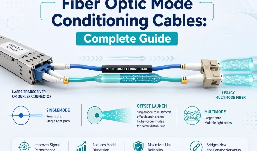
A fiber optic mode conditioning cable is a specialized duplex patch cable used when certain laser based transceivers, most commonly 1000BASE LX or 1000BASE LH modules, must operate over older multimode fiber. Its transmit strand launches the optical signal away from the centre of the multimode core. This controlled offset launch reduces differential mode delay and helps the link operate more reliably. A typical duplex link requires one mode conditioning cable at each end, and the cable must match the installed 50/125 or 62.5/125 micron fiber.
What this guide covers
- What is a mode conditioning cable?
- Why these cables are needed
- How offset launch works
- Cable comparison
- Common applications
- Fiber type compatibility
- Distance requirements
- How to select the correct cable
- Installation guide
- Testing and verification
- Troubleshooting
- Use mode conditioning or replace the fiber?
- Frequently asked questions
Fiber networks often contain equipment and cabling from different generations. A building may still have a dependable OM1 or OM2 multimode backbone between telecommunications rooms, while its network switches have been replaced with equipment using newer laser based optical transceivers.
Both parts of the system may still be useful, but connecting them with an ordinary multimode patch cable is not always correct. In some applications, the optical signal can experience differential mode delay, reduced usable bandwidth, increased errors, or an unstable link.
A mode conditioning cable provides a practical way to connect certain compatible long wavelength transceivers to legacy multimode fiber. It does this without electrical power, active electronics, or protocol conversion. The cable changes the way light is launched into the multimode core.
What is a fiber optic mode conditioning cable?
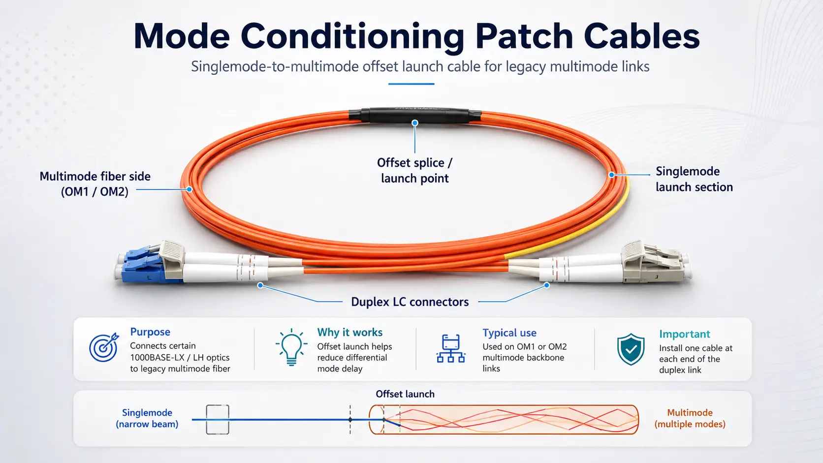
A fiber optic mode conditioning cable, also called a mode conditioning patch cable, mode conditioning patch cord, or MCP cable, is a specialized duplex fiber assembly used to connect a compatible optical transceiver to a legacy multimode fiber cable plant.
The cable normally contains two different optical paths:
- Transmit path: A short singlemode fiber section is permanently joined to multimode fiber through a carefully controlled offset connection.
- Receive path: A conventional multimode fiber strand carries the returning signal back to the transceiver.
The offset connection is what makes the cable different from a regular duplex jumper. It moves the transmit signal away from the exact centre of the multimode core, creating an offset launch.
Important distinction
A mode conditioning cable is not a media converter, signal amplifier, wavelength converter, or network extender. It is a passive optical assembly designed for a specific transceiver and fiber combination.
Why are mode conditioning cables needed?
figure>
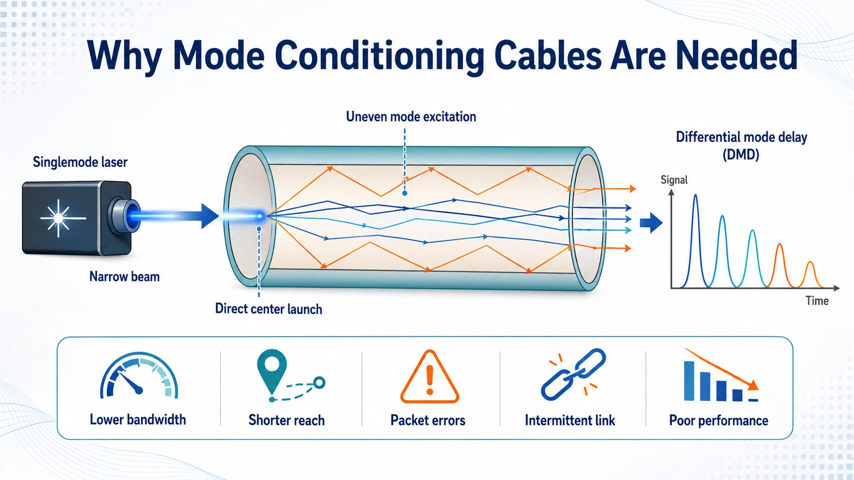
Multimode fiber has a larger core than singlemode fiber. This larger core allows light to travel along several optical paths, called modes. Some modes travel close to the centre. Others travel at wider angles and follow longer paths.
A singlemode laser produces a narrow and highly concentrated optical signal. When this signal is launched directly into the centre of older multimode fiber, it can excite the available modes unevenly. Portions of the optical pulse may then reach the receiver at slightly different times.
This condition is called differential mode delay, often shortened to DMD.
Differential mode delay can contribute to:
- Reduced usable bandwidth
- Shorter supported transmission distance
- Packet errors and retransmissions
- Interface errors or frame check sequence errors
- An unstable link that drops intermittently
- A link that comes online but performs poorly under load
- A link that fails to establish consistently
Plain language explanation
The laser pulse may enter the old multimode fiber too precisely and travel through the core unevenly. The mode conditioning cable deliberately moves that launch point away from the centre so the signal travels through a more suitable group of modes.
How does the offset launch work?
The transmit side of the cable begins with singlemode fiber at the equipment connector. That singlemode strand is joined to multimode fiber through a precisely positioned splice or coupling point.
The singlemode core is deliberately offset from the exact centre of the multimode core. When the transceiver sends its signal, the light enters the multimode fiber away from the centre and uses a more suitable group of modes.
- The signal travels through the singlemode section.
- It reaches the offset singlemode to multimode connection.
- The optical energy enters the multimode core away from its centre.
- The installed multimode backbone carries the signal to the remote room.
- The remote receiver receives a cleaner and more predictable signal.
The receive strand normally uses conventional multimode fiber. Since each end has a transmitter, a complete duplex link usually requires two mode conditioning cables, one at each end.
Mode conditioning cable versus standard fiber patch cables
| Feature | Standard multimode cable | Mode conditioning cable | Standard singlemode cable |
|---|---|---|---|
| Construction | Multimode fiber on both strands | Offset singlemode to multimode transmit strand plus multimode receive strand | Singlemode fiber on both strands |
| Purpose | Connect multimode equipment to multimode cabling | Connect compatible laser transceivers to legacy multimode cabling | Connect singlemode equipment to singlemode cabling |
| Typical core size | 50/125 or 62.5/125 micron | Singlemode launch into 50/125 or 62.5/125 micron multimode fiber | 9/125 micron |
| Offset launch | No | Yes, on the transmit strand | No |
| Used with 1000BASE SX | Yes, when compatible | No | No |
| Used with 1000BASE LX over OM1 or OM2 | Not when mode conditioning is required | Yes, when specified | No, unless the complete cable plant is singlemode |
| Requires power | No | No | No |
When is a mode conditioning cable used?
Mode conditioning cables are most closely associated with compatible 1000BASE LX and 1000BASE LH Gigabit Ethernet transceivers operating over older multimode fiber.
A typical application includes:
- A compatible long wavelength optical transceiver
- A laser source operating near 1300 or 1310 nanometres
- An installed OM1 or OM2 multimode backbone
- A duplex optical connection
- One correctly selected mode conditioning cable at each end
Certain older 10 Gigabit Ethernet applications may also specify mode conditioning over legacy multimode fiber. Always check the exact switch, line card, GBIC, SFP, SFP Plus, or transceiver documentation.
| Application | Installed fiber | Mode conditioning | General guidance |
|---|---|---|---|
| 1000BASE LX or LH | OM1 62.5/125 | Commonly required | Use a 62.5 micron mode conditioning cable |
| 1000BASE LX or LH | OM2 50/125 | May be required | Use a 50 micron mode conditioning cable |
| 1000BASE SX | Compatible multimode | Do not use | Use a standard matching multimode patch cable |
| 1000BASE LX or LH | OS2 singlemode | Do not use | Use a standard OS2 patch cable |
| 10GBASE SR | OM3 or OM4 | Do not use | Use a standard laser optimized multimode cable |
| 10GBASE LRM | Legacy multimode | May be specified | Follow exact manufacturer documentation |
OM1, OM2, OM3, OM4, and OS2 compatibility
OM1 multimode fiber
OM1 normally uses a 62.5/125 micron construction and is common in older offices, schools, warehouses, plants, hospitals, and campuses. When the installed backbone is OM1, use a mode conditioning cable designed for 62.5/125 micron multimode fiber.
OM2 multimode fiber
OM2 normally uses a 50/125 micron construction. Although its core is smaller than OM1, it is still legacy multimode fiber in many current designs. When the backbone is OM2, select a cable designed for 50/125 micron multimode fiber.
OM3 and OM4 multimode fiber
OM3 and OM4 are laser optimized 50/125 micron fibers. They are normally used with compatible short range multimode transceivers and standard OM3 or OM4 patch cables. Do not add mode conditioning simply because the cable plant is multimode.
OS1 and OS2 singlemode fiber
Mode conditioning is not used when a compatible singlemode transceiver connects to an OS1 or OS2 cable plant. Use a standard singlemode patch cable with the correct connector type and polish.
Do not identify fiber by colour alone
Orange, aqua, violet, and yellow jackets provide useful clues, but older installations are not always labelled consistently. Confirm the fiber type through jacket markings, test reports, as built drawings, patch panel records, or professional testing.
Does distance determine whether mode conditioning is required?
Distance matters, but it should not be the only decision point. Some older equipment manuals discuss mode conditioning mainly for links beyond a stated distance. Other transceiver documentation requires it on supported multimode links regardless of length.
The correct requirement depends on:
- The exact transceiver part number
- The switch or line card model
- The installed fiber classification
- The multimode core size
- The total link length
- The number of connectors and splices
- The optical loss budget
- The manufacturer installation requirements
Avoid the common 300 metre assumption
Do not assume that a short multimode link can always use a regular patch cable. If the transceiver documentation requires mode conditioning, follow that requirement even when the span is shorter than a commonly quoted threshold.
A compatible Gigabit Ethernet application may support up to approximately 550 metres over certain multimode cable plants when the correct launch condition and optical budget are provided. Actual reach depends on fiber bandwidth, cable condition, connector loss, splice quality, transceiver specifications, and system margin.
How to choose the correct mode conditioning cable
| Required information | Example | Why it matters |
|---|---|---|
| Transceiver model | Cisco GLC LH SM | Confirms support and cabling requirements |
| Operating wavelength | 1310 nanometres | Confirms the optical application |
| Installed fiber | OM1 | Identifies the legacy multimode type |
| Core size | 62.5/125 micron | Determines the correct launch geometry |
| Equipment connector | LC duplex | Determines the transceiver side connector |
| Panel connector | SC duplex | Determines the network side connector |
| Connector polish | UPC | Prevents UPC and APC mismatch |
| Length | 3 metres | Allows proper rack routing |
| Quantity | Two per duplex link | Provides conditioning at both transmitters |
Confirm the complete transceiver part number
Do not rely only on labels such as LX, LH, or long range. Similar looking modules may have different wavelength, distance, connector, and cabling requirements.
Match the installed core size
A 62.5 micron mode conditioning cable is not automatically suitable for a 50 micron cable plant. The offset geometry and multimode section must match the installed fiber.
Confirm both connector ends
Modern SFP modules usually use duplex LC connectors, while older patch panels may use SC. Common assemblies include LC to LC, LC to SC, SC to SC, and SC to LC.
Confirm connector polish
Most Ethernet equipment uses UPC polished connectors. UPC and APC connectors should not be directly mated because the end face geometry is different.
Select a practical length
The cable should follow the rack management path without being stretched, tightly coiled, crushed, or bent below its rated bend radius.
Need the correct mode conditioning cable?
Cablify supplies standard and custom fiber optic cable assemblies. Provide the transceiver model, installed fiber type, core size, connector combination, length, and quantity, and our team can help identify the correct assembly.
How to install a mode conditioning cable
Confirm the application
Verify the transceiver, fiber type, core size, connector type, supported reach, and manufacturer requirement.
Protect the optical interface
Follow the equipment procedure before disconnecting an active link. Never look into an optical transceiver or fiber connector.
Inspect every end face
Inspect the transceiver interface, both ends of each patch cable, and the patch panel adapters with a suitable fiber inspection scope.
Clean and inspect again
Use an approved fiber cleaning method when contamination is visible. Inspect again before connection.
Identify the conditioned transmit strand
Locate the strand marked TX, transmit, singlemode launch, or offset launch.
Connect the equipment side correctly
The singlemode launch strand must connect to the transmitter side of the optical module.
Connect the multimode side
Connect the opposite end to the existing multimode patch panel and confirm polarity, connector type, and polish.
Repeat at the remote end
Install the second mode conditioning cable and again connect its conditioned strand to the transmitter.
Restore and verify the link
Check link status, optical power, alarms, interface counters, and stability under traffic.
How to test a mode conditioned fiber link
Connector inspection
Inspect every accessible connector. Dust, oil, scratches, and damaged end faces can create enough loss to cause failure.
Insertion loss testing
Use an optical loss test set or calibrated light source and power meter to measure end to end insertion loss. Compare the result with a calculated budget that includes fiber attenuation, connector loss, splice loss, and engineering margin.
OTDR testing
An OTDR can help locate high loss connectors, reflective events, poor splices, fiber breaks, macrobends, and unexpected connection points. OTDR testing is valuable for diagnostics but should not automatically replace end to end insertion loss testing.
Active transceiver verification
When digital optical monitoring is available, review transmit power, receive power, module temperature, bias current, alarm thresholds, and warning conditions. Also review interface counters before and after a traffic test.
A green link light is not the complete test
A link may come online while still generating errors or operating with very little optical margin. Confirm optical measurements and interface performance whenever the link is business critical.
Troubleshooting common faults
| Problem | Possible cause | Recommended check |
|---|---|---|
| No link | Incorrect TX and RX polarity | Trace both strands end to end |
| No link | Conditioned strand connected to RX | Connect the singlemode launch strand to TX |
| No link | Only one mode conditioning cable installed | Confirm one cable is installed at each end |
| No link | Wrong connector or polish | Verify LC, SC, UPC, and APC compatibility |
| Intermittent link | Dirty connector | Inspect, clean, and inspect all connections |
| Intermittent link | Wrong core size | Confirm 50/125 or 62.5/125 micron fiber |
| High error count | Mode conditioning missing | Check the exact transceiver documentation |
| Low receive power | Excessive link loss | Calculate the optical budget and test loss |
| Unexpected loss | Damaged connector, bend, splice, or fiber | Inspect connectors and perform OTDR testing |
| Correct cable still fails | Unsupported equipment and fiber combination | Verify manufacturer compatibility |
Should you use mode conditioning or replace the fiber?
A mode conditioning cable can extend the useful life of a suitable legacy multimode backbone. It may reduce cost, avoid disruption, and support a controlled network upgrade.
Fiber replacement may be the better long term decision when the existing cable is damaged, poorly documented, short on available strands, outside the required loss budget, or unable to support planned network speeds.
| Situation | Mode conditioning may be suitable | Replacement may be better |
|---|---|---|
| Cable condition | Documented and within loss limits | Damaged, unknown, or repeatedly failing |
| Required speed | Current application is fully supported | Higher speeds are planned soon |
| Available strands | Enough serviceable fibers remain | Too few fibers remain for growth |
| Pathway access | Replacement would be highly disruptive | Pathways are open during construction |
| Optical budget | Comfortably within limits | Connections and splices consume too much margin |
| Long term standard | Legacy link has a defined service life | The network is standardizing on OS2 |
Professional fiber identification, termination, and testing
When the installed fiber type is unknown or a link is unstable, replacing patch cords without testing can waste time and money. Cablify provides commercial fiber inspection, termination, fusion splicing, insertion loss testing, OTDR testing, fault location, labelling, and commissioning.
Our network cabling team supports offices, warehouses, industrial facilities, campuses, data centres, and multi building networks.
Frequently asked questions
What does a mode conditioning cable do?
It changes how a compatible laser signal enters legacy multimode fiber. The transmit strand launches the signal away from the centre of the core, helping reduce differential mode delay.
Is a mode conditioning cable a singlemode cable?
Not exactly. Its transmit strand begins with singlemode fiber and then joins multimode fiber through an offset connection. Its receive strand normally uses multimode fiber.
When is a mode conditioning cable required?
It is commonly associated with compatible 1000BASE LX or 1000BASE LH transceivers operating over OM1 or OM2 multimode fiber. Follow the exact equipment documentation.
Do I need one at both ends?
Yes. A typical duplex link requires one mode conditioning cable at each transceiver.
Can I use a regular OM1 or OM2 patch cable?
Not when the manufacturer requires mode conditioning. A regular multimode jumper does not provide the controlled offset launch.
Can I use a standard singlemode patch cable?
No. A standard singlemode cable does not provide the required offset transition into the multimode cable plant.
Can I use it with 1000BASE SX?
No. Normal 1000BASE SX applications use compatible multimode transceivers and standard multimode patch cables.
Can I use it with OS2 fiber?
No. A compatible singlemode transceiver connected to OS2 should use standard OS2 singlemode patch cables.
What is the difference between 50 and 62.5 micron versions?
The multimode core size and offset launch geometry are different. Match the cable to the installed fiber.
Will it increase network speed?
No. It does not increase the rated Ethernet speed. It helps a supported optical application operate more reliably.
Can it repair damaged fiber?
No. It cannot correct broken fibers, dirty connectors, damaged end faces, poor splices, severe bends, excessive loss, or unsupported distance.
Can the link be tested with an OTDR?
Yes. An OTDR can help locate faults, but insertion loss testing and active transceiver verification may also be required.
Are mode conditioning cables still used?
Yes. They remain relevant where compatible laser based transceivers must operate over suitable OM1 or OM2 infrastructure.
Technical note: Transceiver support varies by manufacturer, platform, module revision, fiber type, and link length. Confirm the exact equipment documentation before purchasing or installing a mode conditioning cable.