
Let’s Start With a Few Questions
Before we dive into specifications and standards, consider your own network experience:
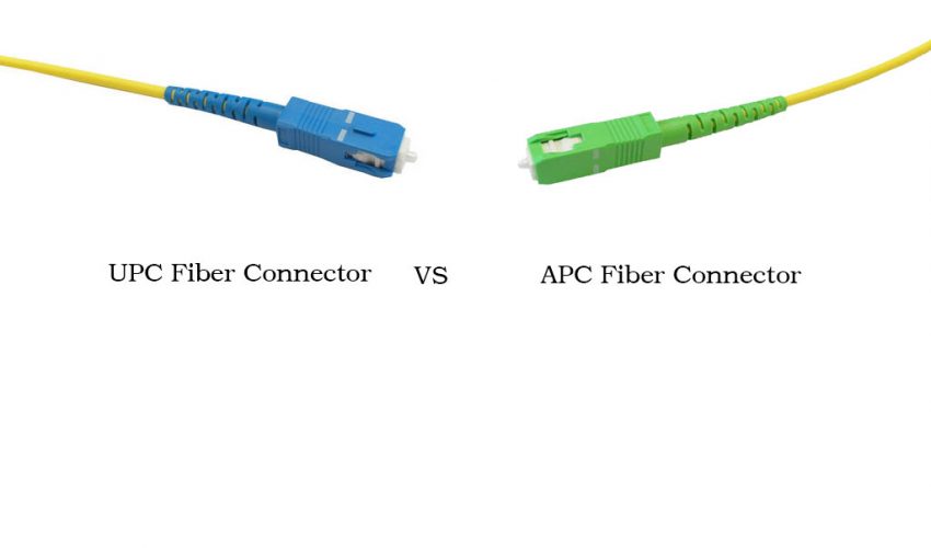
- Have you ever noticed different colored connectors on fiber cables and wondered why?
- Have you replaced a connector but still seen unexplained signal loss or poor test results?
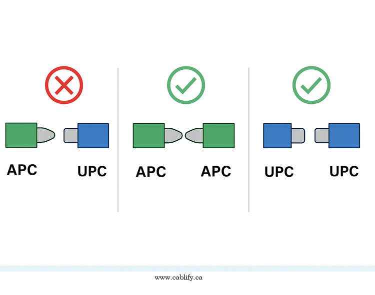
- Do you know why a green connector can’t be connected to a blue one, even if the connectors physically fit?
- Have you heard of return loss but aren’t exactly sure how it impacts your transmission quality?
Among the most important factors affecting performance is the connector end-face polish type, which determines signal loss (insertion loss) and back reflection (return loss). The three primary polishing types are:
- PC (Physical Contact)
- UPC (Ultra Physical Contact)
- APC (Angled Physical Contact)
This guide explores the technical differences, applications, and performance characteristics of PC, UPC, and APC connectors, helping engineers, network designers, and technicians make informed decisions. Whether your fiber cabling project involves short in-building runs or long-haul telecom links, understanding the difference between PC, UPC, and APC connectors ensures maximum network efficiency and signal integrity.
If any of these sound familiar, then this article will give you the clarity you need. By the end, you’ll not only understand what PC, UPC, and APC connectors are, but you’ll know exactly when and why to use each type — and how to avoid the costly mistakes that happen when they’re mismatched.
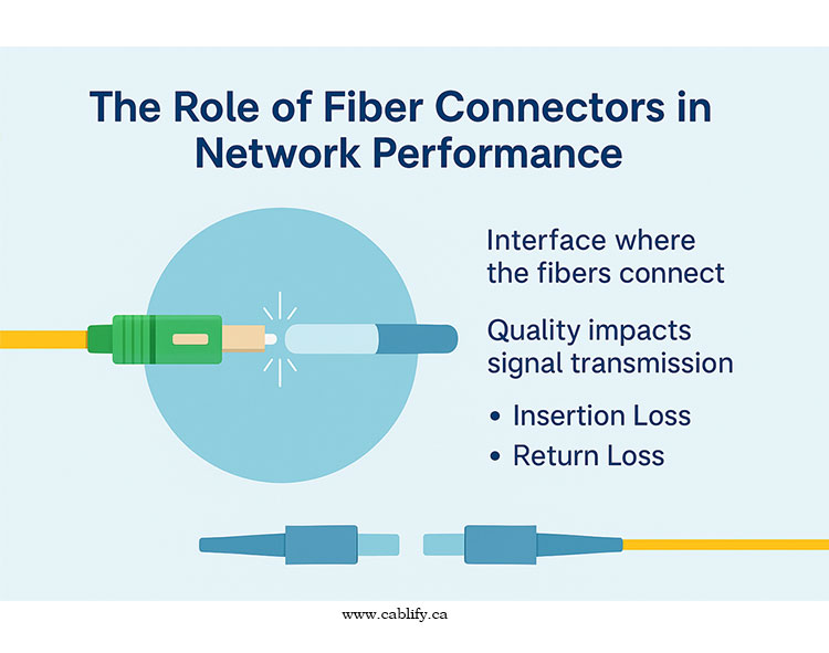
The Role of Fiber Connectors in Network Performance
In any fiber optic system, the connector is the interface between two worlds:
- The glass core that carries your signal.
- The hardware that transmits or receives that signal.
For high-speed optical links, the connector’s quality has a direct impact on:
Insertion Loss (IL) – How much light is lost when it passes through the connection.
Return Loss (RL) – How much light is reflected back toward the source.
Even a perfectly manufactured fiber cable can suffer from degraded performance if the end-face geometry of the connector is poor or mismatched to the application.
Expert Q&A:
Q: Why can’t we ignore connector quality if the fiber itself is good?
A: Because the connector is where most loss and reflection problems occur. Fiber in the middle of a link has no breaks; all the critical alignment happens at the terminations.
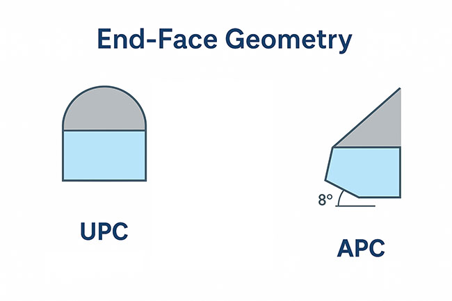
Understanding End-Face Geometry
Definition:
The end-face geometry refers to the shape, angle, and smoothness of the fiber’s exposed end where it meets another fiber.
Key parameters:
- Radius of curvature – Controls the convex shape, ensuring cores meet at the center.
- Apex offset – The distance between the curve’s highest point and the fiber core’s center.
- Polish angle – The tilt of the fiber surface; zero for PC/UPC, typically 8° for APC.
Poor geometry leads to:
- Micro-gaps that increase insertion loss.
- Flat spots that cause higher back reflection.
- Misalignment that reduces effective core-to-core contact.
Infographic idea: Side-by-side micrographic representation of PC, UPC, and APC end-faces under a microscope, with angle and curvature labeled.
UPC (Ultra Physical Contact) Connectors
Why UPC was developed:
As bandwidth needs increased, networks became more sensitive to reflections. UPC was introduced to provide a better polish, reducing microscopic surface imperfections.
Design Features:
- Same convex profile as PC but with a finer polish
- Achieved through extended polishing time and tighter manufacturing tolerances
- Still a 0° angle, so any reflected light travels back toward the source
Performance:
- Return Loss: -50 to -55 dB
- Insertion Loss: 0.1–0.3 dB
Applications:
- Common in modern Ethernet and telecom applications up to 400G
- Data centers, enterprise LAN/WAN, and backbone links
Expert Q&A:
Q: Can UPC be used for analog TV signals over fiber?
A: It can, but it’s not ideal. Analog and high-power signals are more sensitive to reflections, so APC is preferred.
APC (Angled Physical Contact) Connectors
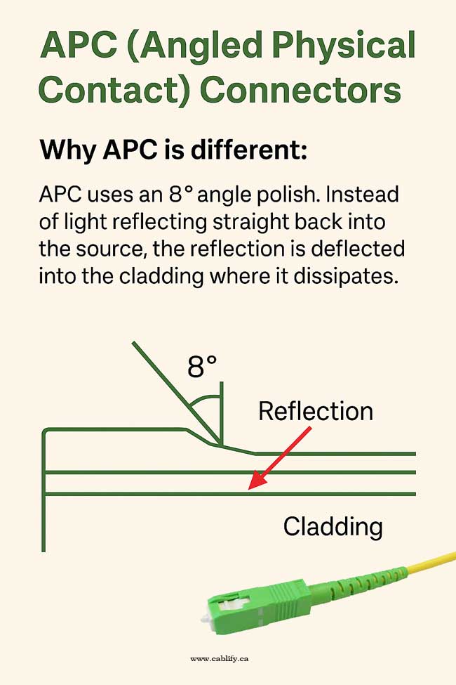
Why APC is different:
APC uses an 8° angle polish. Instead of light reflecting straight back into the source, the reflection is deflected into the cladding where it dissipates.
Design Features:
- Convex + angled ferrule
- Industry-standard angle: 8° ± 0.2°
- Color coded green for easy identification
Performance:
- Return Loss: -60 to -65 dB (high-end models up to -70 dB)
- Insertion Loss: 0.1–0.3 dB
Applications:
- RF over fiber (satellite, CATV)
- Passive Optical Networks (PON)
- Long-haul DWDM systems
Failure Scenario:
Mixing APC and UPC connectors — even though they “fit” — causes catastrophic performance. The cores don’t align properly, leading to very high insertion loss and unpredictable reflections.
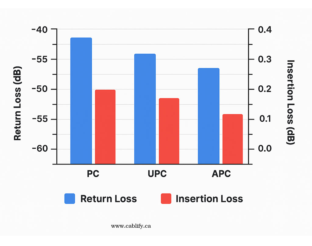
Return Loss & Insertion Loss Comparison
| Connector | Angle | Return Loss | Insertion Loss | Color |
|---|---|---|---|---|
| PC | 0° | ~ -40 dB | 0.2–0.4 dB | Blue/Beige |
| UPC | 0° | -50 to -55 dB | 0.1–0.3 dB | Blue |
| APC | 8° | -60 to -65 dB | 0.1–0.3 dB | Green |
Infographic idea: Dual-axis bar chart showing RL and IL for each type.
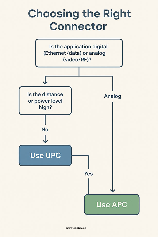
Choosing the Right Connector – Decision Logic
Selecting between UPC, and APC fiber connectors isn’t just a matter of cost — it’s about matching the connector’s optical characteristics to the application type, link budget, and existing infrastructure. Using the wrong polish type can introduce excessive reflections, shorten transmission distances, and even damage sensitive optical components.
To make the decision process straightforward, follow these three steps:
Step 1: Identify Your Application Type – Digital or Analog
Digital Transmission (Ethernet/Data)
-
Includes Ethernet (1G to 400G), Fibre Channel, and most data network protocols.
-
Performance is primarily affected by return loss (RL) and insertion loss (IL), but small amounts of reflection can often be tolerated by digital transceivers.
-
Recommendation:
-
UPC is the default choice for most digital systems because it offers low IL and good RL (-50 to -55 dB), balancing performance and cost.
-
APC can be used if your digital system operates at very high speeds or spans long distances where reflections could become significant.
-
Analog Transmission (Video/RF)
-
Includes CATV (Cable TV), satellite uplinks, broadcast video, and RF over fiber.
-
Analog optical links are highly sensitive to reflections because even a small amount of reflected light can cause signal distortion, noise, and degraded picture/sound quality.
-
Recommendation:
-
Always use APC for analog systems to achieve the lowest possible RL (-60 to -65 dB), ensuring signal integrity.
-
Pro Tip: If in doubt, ask whether the optical signal is digitally encoded or analog modulated — the answer will almost always determine the polish type.
Step 2: Evaluate Distance and Power Levels
Long-Haul or High-Power Systems
-
Examples: Long-distance DWDM (Dense Wavelength Division Multiplexing), submarine cables, metropolitan backbones, high-power fiber lasers.
-
Long-haul links accumulate more reflections over distance, and high-power systems are more prone to damage from reflected light (optical return can heat up and stress laser diodes).
-
Recommendation:
-
Use APC for its superior reflection control, ensuring stable operation over the entire link life.
-
Short-to-Medium Distance Links
-
Examples: Enterprise LAN, campus networks, short-haul metro fiber.
-
Reflections are less critical because of shorter distances and lower power levels.
-
Recommendation:
-
UPC is fine for most cases, offering good performance without the added cost and handling requirements of APC.
-
Step 3:
Check Existing Infrastructure for Compatibility
Fiber connectors are mechanically compatible between PC and UPC, and between APC types — but they’re not optically compatible if the polish types don’t match.
-
Mating a UPC to an APC results in high IL and RL, creating link instability or outright failure.
-
Always check the connector ferrule color:
-
Blue – UPC/PC singlemode
-
Green – APC singlemode
-
Beige/Aqua – Multimode UPC/PC
-
Recommendation:
-
Match your new connectors to whatever is already installed in the link, unless you plan to replace all terminations.
-
If upgrading part of a system from UPC to APC, ensure all mating hardware and patch cords are also APC.
Standards That Define Quality
IEC 61755 – End-face Geometry
Defines the required physical parameters of fiber optic connector end-faces, such as radius of curvature, apex offset, and fiber height. This ensures low insertion loss and return loss. It also sets tolerances to maintain performance consistency across different manufacturers.
TIA/EIA-568 – Structured Cabling
Covers the design and installation of structured cabling systems for commercial buildings and data centers. It includes specifications for fiber optic cabling types, connector types, polarity, and performance requirements, ensuring compatibility and interoperability.
GR-326-CORE – Connector Durability and Environmental Performance
Specifies mechanical, environmental, and optical performance requirements for single-mode connectors. It covers tests for durability, temperature cycling, humidity, vibration, and contamination to ensure connectors maintain performance over time in real-world conditions.
Maintenance & Testing
Cleaning:
-
PC/UPC: Dry or wet-dry wipes.
-
APC: Use angled cleaning tools to preserve polish angle.
Testing:
-
IL test with power meter + light source.
-
RL test with Optical Return Loss Meter.
-
Follow IEC 61300-3-6 for repeatable results.